FGT think your best choice in the future
System Integration Designers in FGT
- Description
- Additional information
- Technical Specifications
- Application
- Flow range
- Ordering Information
- certified
- Special needs
- Inquire now
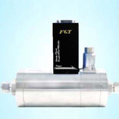
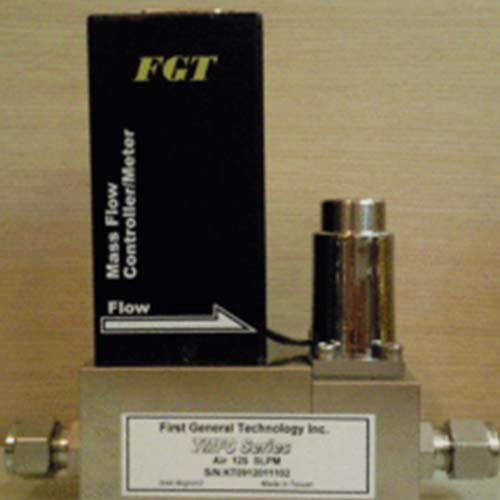
TMFC500 Mass Flow Controller Features | Gas Flow Control
- High accuracy at low flow
- Fast response (≦1.0)
- Wide pressure range available (1300 PSIG)
- No leakage
- No temperature or pressure required
- connection compatible
- Detachable sensor for high stability
- Corrosion resistance value
- excellent linearity
- Excellent long-term stability
- Modular design
- Compact Flow Control System
Product Videos
benefit:
Mass Flow Controller Applications
- Plasma Cleaner
- Gas diverter valve box/panel
- Gas cylinder cabinet output flow control
- Gas generator output control
- flame welding control
What types of mass flow controllers exist in the TMFM/TMFC series?
Thermal mass flow controllers use the thermal mass sensing technique of gases to control their mass flow. In the TMFC portfolio we have several thermal mass flow controllers, each with its own sensor technology:
Mass flow controllers using bypass sensors. These devices, such as TMFCs and TMFMs, are ideal for clean and dry gas applications where greater precision and repeatability are required.
Mass flow controller using the on-line principle. Series such as the TMFC and TMFM series are perfect if your application has high purity gases above 99.9%, or when high repeatability and robustness are more important than accuracy.
Gas mass flow controller using piping control technology. These series stand out because they can measure gas flow and control.
Whenever your mass flow needs to be displayed and over a wide flow range, a gas series using MEMS chip sensor technology such as the TMFM6000 is perfect.
Gas mass flow controllers using in-line (CMOS) technology.
Mass Flow Controller ( MFC ) Principle / Flow Controller Principle
A mass flow controller (MFC) is a device used to measure and control the flow of liquids and gases. [1] Mass flow controllers are designed and calibrated to control a specific type of liquid or gas over a specific flow range. The MFC can have a set point between 0% and 100% of its full scale range, but typically operates within the full scale range of 10% to 90% for best accuracy. The device will then control the flow rate to the given set point. MFCs can be analog or digital. Digital flow controllers are usually capable of controlling more than one fluid, while analog controllers are limited to the fluids they are calibrated for.
All mass flow controllers have an inlet port, an outlet port, a mass flow sensor, and a proportional control valve. The MFC is equipped with a closed loop control system where the operator (or external circuit/computer) provides an input signal which is compared with the value of the mass flow sensor and adjusts the proportional valve accordingly to achieve the desired flow. Flow is specified as a percentage of its calibrated full scale flow and is provided to the MFC as a voltage signal.
Mass flow controllers require the supply gas or liquid to be within a specific pressure range. Low pressure will deplete the MFC of fluid and prevent it from reaching its set point. High pressures may cause erratic flow rates. There are many different technologies that help measure the flow of fluids and ultimately help control flow. These technologies define the types of mass flow controllers and they include differential pressure (ΔP), differential temperature (ΔT), Coriolis force, ultrasonic, electromagnetic, turbine, etc.

Mass Flow Meter Installation
Now there are more and more applications of mass flowmeters, and some occasions where mass flowmeters are installed for the first time are not clear about the installation method of mass flowmeters, reverse installation, wrong installation, etc., which affect the normal use of the equipment. This article discusses this problem Describe in detail how to install a mass flow meter.
Excessive mechanical stress during sensor installation will affect the zero point of the mass flowmeter. If these stresses are constantly changing, the zero point drift of the meter will cause inaccurate measurement and cannot work normally. Therefore, the correct installation of the mass flowmeter is an important part of ensuring the normal operation of the equipment.
1. Choose the installation method
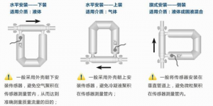
The installation method of the sensor is mainly determined according to the phase difference of the fluid and its process conditions. There are three installation methods.
1. If the measured fluid is a liquid, the sensor is generally installed with the shell facing down to avoid air accumulation in the vibrating tube of the sensor, so as to achieve the purpose of accurately measuring the mass flow rate.
2. If the measured fluid is gas, the sensor is generally installed with the shell facing upwards to avoid accumulation of condensate in the sensor vibration tube.
3. If the measured fluid is a mixed slurry of liquid and solid, install the sensor on a vertical official road, which can prevent particles from accumulating in the sensor's Coriolis force measuring tube. In addition, if the process pipeline needs to be cleaned with gas and steam, this installation method can also facilitate cleaning, but this installation method is more difficult to fix than the previous two, and the pressure loss is larger.
gas flow controller
gas mass flow controllers
Mass Flow Formula
Types of mass flow meters
mass flow meter english
according toThree degrees Chinese website.Multiple interpretations mass flowmeter【electronic computer term】mass flow meter【mechanical engineering】mass flowmeter sensor【marine science term-underwater engineering】thermal mass flow【electronic engineering】mass flow measurement【electrical engineering】
| Application | Factory |
|---|---|
| Types of | Electronic |
| Installation method | Thread |
| Output method | digital, analog |
Technical Specifications
| model | TMFC500V | TMFC500VD | TMFC500A | TMFC500AD | |
| Flow range (nitrogen) | 300~1000SLM | 300~1000SLM | 300~1000SLM | 300~1000SLM | |
| reaction speed | ≦2.0sec | ||||
| precision | ±1.0 % FS | ||||
| Repeat accuracy | ±0.25 % FS | ||||
| Pressure resistance | 1500 PSIG | ||||
| leak rate | 1 x 10⁻⁹ atm.cc/sec or less | ||||
| operating temperature | 0~50℃ | ||||
| Main body SUS316 | |||||
| Accessories material | Body Gasket Vition™ (Option Bura™ or Kalrez™ or Teflon™) | ||||
| Standard: 1/2″ compression | |||||
| Connection method | Optional: 1/4″ Compression or VCR™, 3/8″ Compression or VCR™ | ||||
| electrical wiring | Dsub 15-pin male connector single outlet | ||||
| Traffic signal input | 0~5Vdc | 0~5Vdc+RS-485 | 4~20mA | 4~20mA+RS-485 | |
| Flow signal output | 0~5Vdc | 0~5Vdc+RS-485 | 4~20mA | 4~20mA+RS-485 | |
| Supply voltage | +15~28Vdc/350mA | ||||
| Applicable type | ◎Support | without | ◎Support | without | |
| Dashboard Type | Optional: Integrated type or separate type (interface cable 1m or 3m) only for TMFC500V/A application | ||||
| Optional display panel | show communication interface | Digital Communication: RS485 (default) / DeviceNet™ only for TMFC500V/A application | |||
| Supply voltage | AC110~240 V only for TMFC500V/A application | ||||
Application
What is MFC
A mass flow controller (MFC) is a device used to measure and control the flow of gas. [1] Mass flow controllers are designed and calibrated to control a specific type of liquid or gas within a specific flow rate range. The MFC can be set from 0% to 100% of its full scale range, but typically operates within the range of 10% to 90% of full scale for best accuracy. The device will then control the flow rate to the given setpoint. MFCs can be either analog or digital. Digital flow controllers are often capable of controlling more than one type of fluid, while analog controllers are limited to the fluid for which they are calibrated.
All mass flow controllers have an inlet, an outlet, a mass flow sensor and a proportional control valve. The MFC houses a closed loop control system to which the operator (or external circuit/computer) provides an input signal which compares it to the value of the mass flow sensor and adjusts the proportional valve accordingly to achieve the desired flow. Flow is specified as a percentage of its calibrated full-scale flow and is provided to the MFC as a voltage signal.
Mass flow controllers require that the gas or liquid supplied must be within a specific pressure range. Low pressure can starve the MFC of liquid and prevent it from reaching the set point. High pressure can cause unstable flow.
MFC application
1. CVD equipment
What is CVD
Semi-Vapor Deposition (CVD) is a vacuum deposition method used to produce high-quality, high-performance solid materials. This process is commonly used in the semiconductor industry to produce thin films.
In typical CVD, the wafer (substrate) is exposed to one or more volatile precursors that react and/or decompose on the surface of the substrate to produce the desired deposit. Volatile by-products are also typically produced, which are removed by the gas flow through the reaction chamber.
Microfabrication processes widely use CVD to deposit various forms of materials including: single crystal, polycrystalline, amorphous and epitaxy. These materials include: silicon (carbon dioxide, carbides, nitrides, oxynitrides), carbon (fibers, nanofibers, nanotubes, diamond and graphene), fluorocarbons, filaments, tungsten, titanium nitride and various high k dielectric.
2. Valve Box/Panel (VMB/VMP)
What is VMB/VMP
Through our experience in handling gases, we have gained the knowledge to design and manufacture panels (gas boxes) for EPI systems, MOCVD, material supply systems and more.
Among our business achievements, we are able to design and manufacture products that meet customer requirements (price and specifications). We can handle not only normal gas but also liquefied gas supply for hub rings. We also support various legal applications.
Flow range
| model | TMFC500V | TMFC500VD | TMFC500A | TMFC500AD | |
| Flow range (nitrogen) | 300~1000SLM | 300~1000SLM | 300~1000SLM | 300~1000SLM | |
| reaction speed | ≦2.0sec | ||||
| precision | ±1.0 % FS | ||||
| Repeat accuracy | ±0.25 % FS | ||||
| Pressure resistance | 1500 PSIG | ||||
| leak rate | 1 x 10⁻⁹ atm.cc/sec or less | ||||
| operating temperature | 0~50℃ | ||||
| Main body SUS316 | |||||
| Accessories material | Body Gasket Vition™ (Option Bura™ or Kalrez™ or Teflon™) | ||||
| Standard: 1/2″ compression | |||||
| Connection method | Optional: 1/4″ Compression or VCR™, 3/8″ Compression or VCR™ | ||||
| electrical wiring | Dsub 15-pin male connector single outlet | ||||
| Traffic signal input | 0~5Vdc | 0~5Vdc+RS-485 | 4~20mA | 4~20mA+RS-485 | |
| Flow signal output | 0~5Vdc | 0~5Vdc+RS-485 | 4~20mA | 4~20mA+RS-485 | |
| Supply voltage | +15~28Vdc/350mA | ||||
| Applicable type | ◎Support | without | ◎Support | without | |
| Dashboard Type | Optional: Integrated type or separate type (interface cable 1m or 3m) only for TMFC500V/A application | ||||
| Optional display panel | show communication interface | Digital Communication: RS485 (default) / DeviceNet™ only for TMFC500V/A application | |||
| Supply voltage | AC110~240 V only for TMFC500V/A application | ||||
Ordering Information
| Order model | ||||||||||
| TMFC | coding | Flow range | ||||||||
|
|
125 | 30~100SLM | ||||||||
| 300 | 100~300SLM | |||||||||
| 500 | 300~1000SLM | |||||||||
|
|
coding | input/output signal | ||||||||
| V | 0~5Vdc (standard type) | |||||||||
| A | 4~20mA | |||||||||
| VD | 0~5Vdc+RS-485 (cannot be used with optional panel) | |||||||||
|
4~20mA+RS-485 (cannot be used with optional panel) | |||||||||
| coding | Connection method | |||||||||
| 2 | 1/8″ | |||||||||
| 4 | 1/4″ | |||||||||
| 6 | 3/8″(Standard type: suitable for TMFC125/300) | |||||||||
| 8 | 1/2″(Standard type: suitable for TMFC500) | |||||||||
|
|
coding | Connection type | ||||||||
| A | Compression SWL | |||||||||
| V | Male VCR | |||||||||
|
|
coding | Body Gasket | ||||||||
| V | Viton (standard type) | |||||||||
| B | Buna | |||||||||
| K | Kalrez | |||||||||
| T | Teflon | |||||||||
| coding | Optional display panel function #1 | |||||||||
| N | None (standard type) | |||||||||
| I | All-in-one | |||||||||
| D | Separate type with 1 meter cable | |||||||||
| E | Separate type with 3m cable | |||||||||
| Code | Optional display panel function #2 | |||||||||
| F | Digital: Rs-485 (standard type) | |||||||||
| C | DeviceNet™ | |||||||||
|
|
||||||||||
| TMFC | Complete order model | |||||||||
| *Note: All series models use supply voltage (+15~28 Vdc/350mA) | ||||||||||
| *Note: The annual purchase order of the customized brand needs to be more than 100 sets | ||||||||||
certified


