FGT think your best choice in the future
System Integration Designers in FGT
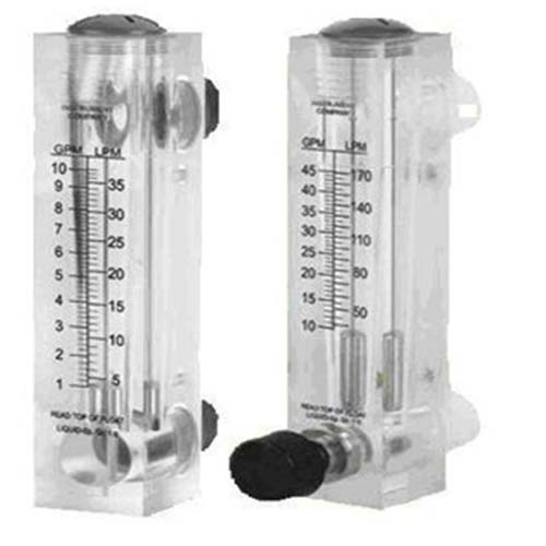
PFB240 Type: Area Flowmeter | Rotameter
PFB240 Type: Area Flowmeter | Rotameter | Application: General Fluid | Laboratory Fluid |: Scrubber | Pure Water Cleaning of Wet Process PCB | RO Pure Water Treatment Equipment | Swimming Pool Treatment Equipment |
Applicable pipe diameter: 1/4" inch internal thread or 1/4" external thread installation
PFB240 Type: Area Flowmeter | Rotameter
- Application: Gases and liquids.
- Wetted Parts Material: Body - Acrylic Plastic O-Ring - NBR, Float-SS316
- Valve material: SS316L
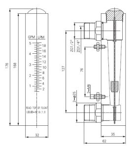
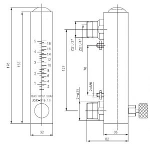
- Connection size: G 1/2" (male) & 1/4" (female)
- Mounting: Vertical position
- Maximum Pressure: 150 Psig (10bar) at 38°C (100°F).
- Temperature: ~+70℃
- Accuracy: FS±3%
Area flow meter
Introduce
Area flow meterIt is a differential pressure flow meter. These are simple and versatile devices for measuring the flow of liquids, gases and steam. They work with a fairly constant pressure drop. In these types of flow meters, a direct visual indication of flow is given by the position of a float, piston or vane. The position of their floats, pistons or vanes changes as rising flow rates open up a larger flow area for the flowing fluid to pass through. When flow is reduced, gravity or springs are used to return the flow element to its static position. Gravity flow meters must also be installed in a vertical position, whereas spring-loaded flow meters can be installed in any position. Each variable area flow meter has a local indicator. In addition, they can be equipped with position sensors and transmitters, i.e. pneumatic, electronic, digital or fiber optic type sensors, for linking to remote displays or controls.
The area flowmeter is composed of a vertical tapered tube that expands from bottom to top and a float with a circular cross-section. The float is moved by the force of the fluid flowing from bottom to top, and the volume of flow is calculated through the area of the fluid. Flow meter, widely used in electric power, petrochemical, chemical, sewage treatment and other industries
Area flow metertype
Area flow meterAvailable in the following designs
- Rotameter (with float in conical tube)
- Orifice/rotameter combination, i.e. bypass rotameter
- Open channel variable gate
- Cone Quick Plug, and
- Vane or Piston Design
Rotameter
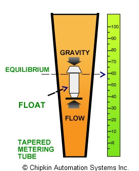
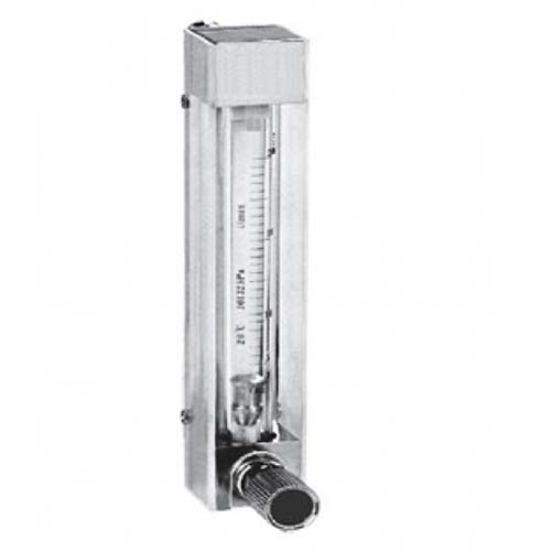
Rotameteris the most widely used variableArea flow meter.RotameterBasically it consists of a vertically oriented glass or plastic conical tube and a metering float that can move freely inside the tube. Rotameters, although classified as differential pressure units, are actually constant differential pressure devices. Flange end fittings provide an easy way to install them in pipes. The float is free to rest on the bottom of the tube when there is no fluid flow. When the liquid enters the bottom of the tube, the metering float begins to rise. The position of the float varies directly with the flow. The precise position of the float is where the pressure difference between the upper and lower surfaces balances the weight of the float. The greater the flow, the higher the float is lifted. In the case of a fluid, the float rises due to a combination of the buoyancy of the liquid and the velocity head of the fluid, whereas with a gas the buoyancy is negligible and the float responds to a large extent to the velocity head. The figure below shows a typical rotameter:
main feature
- existRotameter, the height of the float indicates the flow.
- RotameterTubes can be calibrated and indexed with appropriate flow units.
- RotameterThe turndown ratio is usually as high as 12:1.
- Accuracy may be up to 1% of full scale rating.
- RotameterTubes can be made of glass, metal or plastic.
- Tube diameters range from 1/4 to greater than 6 in.
- In safe applications such as air or water,RotameterThe tubes can be made of glass, while they come with metal tubes in cases where a rupture could lead to an unsafe condition.
- Also, for higher pressures and temperatures above the practical range of glass, metal tubing is usedRotameter.
- plastic pipeRotameteris medium costRotameter. Also, they are ideal for applications involving corrosive fluids or deionized water.
- Almost all rotameters are insensitive to viscosity changes. The most sensitive are extremely small with spherical floatsRotameter, while larger rotameters are less sensitive to viscosity effects.
- Rotameters including magnetic floats can be used for alarm and signaling functions.
- Since the flow rate can be read directly on the scale installed next to the tube, no auxiliary flow reading device is required. However, an automatic sensing device can still be used to sense the float level and send a flow signal if desired.
- Each float position corresponds to a specific flow rate for a specific fluid density and viscosity. Therefore, sizing the rotameter for each application is critical. If properly sized, the flow rate can be determined by matching the float position to a calibrated scale on the outside of the rotameter.
- Many rotameters have built-in valves for manual flow adjustment.
- Various shapes of floats are available for various applications. One early float design had slots, which caused the float to rotate for stabilization and centering. Due to this rotation of the float, the term rotameter was coined.
Rotametersize of
Rotameters typically have calibration data and direct reading scales for air or water or both. In order to size a rotameter for other services, the actual flow must first be changed to a standard flow. In the case of liquids, the standard flow should be the water equivalent in gpm, while when it comes to gas, the expected standard flow is the air flow in standard cubic feet per minute (scfm).
Rotameter manufacturers provide tables listing standard water equivalent gpm and air scfm values. They should also provide available slide rules, nomograms, or computer software, which is often required for sizing rotameters.
advantage
The main advantages of the rotameter are as follows:
- low cost
- simple design
- low pressure drop
- widely used
- Linear output
How to choose a variable area flowmeter?
Flowmeter
What are the minimum and maximum flows for ?
What are the minimum and maximum process temperatures?
What is the size of the tube?
Would you like to use a direct reading meter or would you accept an inquiry meter?
What precision do you need?
Do you need a valve to regulate flow?
Will there be back pressure?
What is the maximum process pressure?
| Application | Flow Meter |
|---|---|
| Types of | Mechanical |
| Installation method | mouth, plate |
Application field
Variable Area Flowmeter
Introduce
A variable area flowmeter is a differential pressure flowmeter. These are simple and versatile devices for measuring the flow of liquids, gases and steam. They work with a fairly constant pressure drop. In these types of flow meters, a direct visual indication of flow is given by the position of a float, piston or vane. The position of their floats, pistons or vanes changes as rising flow rates open up a larger flow area for the flowing fluid to pass through. When flow is reduced, gravity or springs are used to return the flow element to its static position. Gravity flow meters must also be installed in a vertical position, whereas spring-loaded flow meters can be installed in any position. Each variable area flow meter has a local indicator. In addition, they can be equipped with position sensors and transmitters, i.e. pneumatic, electronic, digital or fiber optic type sensors, for linking to remote displays or controls.
Types of Variable Area Flow Meters
Variable area flow meters are available in a variety of designs:
- Rotameter (with float in conical tube)
- Orifice/rotameter combination, i.e. bypass rotameter
- Open channel variable gate
- Cone Quick Plug, and
- Vane or Piston Design
Rotameter
Rotameters are the most widely used variable area flowmeters. A rotameter basically consists of a vertically oriented glass or plastic conical tube and a metering float that can move freely within the tube. Rotameters, although classified as differential pressure units, are actually constant differential pressure devices. Flange end fittings provide an easy way to install them in pipes. The float is free to rest on the bottom of the tube when there is no fluid flow. When the liquid enters the bottom of the tube, the metering float begins to rise. The position of the float varies directly with the flow. The precise position of the float is where the pressure difference between the upper and lower surfaces balances the weight of the float. The greater the flow, the higher the float is lifted. In the case of a fluid, the float rises due to a combination of the buoyancy of the liquid and the velocity head of the fluid, whereas with a gas the buoyancy is negligible and the float responds to a large extent to the velocity head. The figure below shows a typical rotameter:
main feature
- In a rotameter, the height of the float indicates flow.
- Rotameter tubes can be calibrated and indexed with the appropriate flow units.
- Rotameters typically have turndown ratios as high as 12:1.
- Accuracy may be up to 1% of full scale rating.
- Rotameter tubes can be made of glass, metal or plastic.
- Tube diameters range from 1/4 to greater than 6 in.
- In safe applications, such as air or water, rotameter tubes can be made of glass, while in situations where a rupture could lead to an unsafe condition, they come with metal tubes.
- Additionally, for higher pressures and temperatures above the practical range of glass, metal tube rotameters are used.
- Plastic tube rotameters are medium cost rotameters. Also, they are ideal for applications involving corrosive fluids or deionized water.
- Almost all rotameters are insensitive to viscosity changes. The most sensitive are extremely small rotameters with spherical floats, while larger rotameters are less sensitive to viscosity effects.
- Rotameters including magnetic floats can be used for alarm and signaling functions.
- Since the flow rate can be read directly on the scale installed next to the tube, no auxiliary flow reading device is required. However, an automatic sensing device can still be used to sense the float level and send a flow signal if desired.
- Each float position corresponds to a specific flow rate for a specific fluid density and viscosity. Therefore, sizing the rotameter for each application is critical. If properly sized, the flow rate can be determined by matching the float position to a calibrated scale on the outside of the rotameter.
- Many rotameters have built-in valves for manual flow adjustment.
- Various shapes of floats are available for various applications. One early float design had slots, which caused the float to rotate for stabilization and centering. Due to this rotation of the float, the term rotameter was coined.
Dimensions of the rotameter
Rotameters typically have calibration data and direct reading scales for air or water or both. In order to size a rotameter for other services, the actual flow must first be changed to a standard flow. In the case of liquids, the standard flow should be the water equivalent in gpm, while when it comes to gas, the expected standard flow is the air flow in standard cubic feet per minute (scfm).
Rotameter manufacturers provide tables listing standard water equivalent gpm and air scfm values. They should also provide available slide rules, nomograms, or computer software, which is often required for sizing rotameters.
advantage
The main advantages of the rotameter are as follows:
- low cost
- simple design
- low pressure drop
- widely used
- Linear output
Order model
| Ordering Information | ||||||||||||
| PFB240 | coding | fluid type | ||||||||||
| A | water | |||||||||||
|
|
B | gas | ||||||||||
|
|
coding | Flow range | ||||||||||
| 1 | 0.1~1 GPM/0.5~4 LPM (general water type) | |||||||||||
| 2 | 0.2~2 GPM/1~7 LPM (general water type) | |||||||||||
| 3 | 1.0~5 GPM/2~18 LPM (general water type) | |||||||||||
| 4 | 0.4~4 SCFM/12~120 LPM (gas type) | |||||||||||
| 5 | 0.8~8 SCFM/24~240 LPM (gas type) | |||||||||||
| 6 | 1.6~16 SCFM/48~480 LPM (gas type) | |||||||||||
| 7 | 2.4~240 SCFM/72~720 LPM (gas type) | |||||||||||
|
|
coding | Float Material | ||||||||||
| 1 | stainless steel | |||||||||||
|
|
coding | needle valve | ||||||||||
| W | With needle valve (applicable: water & gas) | |||||||||||
| N | No needle valve (applicable: water) | |||||||||||
|
|
coding | take over | ||||||||||
| BB | back to back | |||||||||||
|
|
coding | Customized printing label | ||||||||||
| F | FGT | |||||||||||
|
customized | |||||||||||
| PFB240 | Complete order model | |||||||||||
| *Note: The number of customized labels must be more than 100 sets a year | ||||||||||||

