FGT think your best choice in the future
System Integration Designers in FGT
FVF Type: Vortex Flowmeter | Vapor Flowmeter
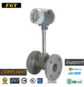
FVF series vortex flowmeter. Designed in line with EX-ATEX/NB-IOT-BMSI-CE certification standards. According to the principle of Karman Vortex Street formation, the number of formed vortices is proportional to the flow velocity to calculate the flow rate of the fluid, suitable for It is suitable for flow measurement of liquid, gas and steam. The original simplified setup and diagnostic functions have temperature and pressure compensation, and multiple outputs can be selected from 4~20mA and MODBUS RTU. Various sizes are available. Temperature range up to 420C. Scratchpad with memory function for setup and calibration. The Wifi function developed by FGT's first general design and production supports SMM cloud sensor software
- Description
- Additional information
- Technical Specifications
- Application field
- Flow range
- Order model
- meet design standards
- Cloud monitoring function
- certified
- Special needs
- Inquire now
- Simplified setup and diagnostics.
- With temperature and pressure compensation
- 4~20mA/pulse output/MODBUS RTU output.
- Various sizes are available.
- Temperature range up to 420oC
- Scratchpad with memory function for setup and calibration.
- Support: NB-IOT development
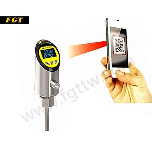
- Wifi function supports SMM cloud sensor software
- Compliant with design standards: EX-ATEX/CE/IP67/UL/IEC/SGS
What is a vortex flowmeter
The composition of the vortex flowmeter
A vortex flowmeter, comprising: a flow sensor operable to sense pressure changes due to vortex shedding of fluid in a channel and convert the pressure changes into flow sensor signals in the form of electrical signals; and a signal processor , which is used to receive the flow sensor signal and generate an output signal corresponding to the change in pressure due to vortex shedding of the fluid in the channel.
working principle
When the medium flows through the Braff body at a certain speed, alternately arranged vortex bands are generated behind the sides of the Braff body, called "von Kalman vortices". Since eddy currents are alternately generated on both sides of the vortex generator, pressure pulsations are created on both sides of the generator, which can cause alternating stress to the detector. The piezoelectric element encapsulated in the detection probe body generates an alternating charge signal with the same frequency as the vortex under the action of alternating stress. The frequency of these pulses is proportional to the flow rate. After the signal is amplified by the preamplifier, it is sent to the intelligent flow accumulator for processing
In a certain range of Reynolds number (2×10^4~7×10^6), the relationship between the vortex release frequency, fluid velocity and the width of the vortex generator facing the flow surface can be expressed by the following formula:
f=St×V/d
where f is the release frequency of the Karman vortex, St is the Strouhal number, V is the velocity, and d is the width of the triangular cylinder.
The application of vortex flowmeter
1. Smart pipeline monitoring application
The main reason for the popularity of flow meters in industrial applications is the way they are designed and manufactured. They have no moving parts, have virtually no obstruction to a straight flow path, require no temperature or pressure correction, and maintain accuracy over a wide flow range. Straight pipe runs can be reduced by the use of double-plate flow conditioning elements, and installation is very simple and does not cause pipe intrusion
However, in many applications the thermal properties of the fluid may depend on the fluid composition. In such applications, changes in fluid composition during actual operation can affect flow measurements. Therefore, it is important for flow meter suppliers to understand the composition of the fluid so that the appropriate calibration factors can be used to accurately determine flow. Vendors can provide appropriate calibration information for other gas mixtures, but the accuracy of the flowmeter depends on the actual gas mixture being the same as the one used for calibration purposes. In other words, the accuracy of a flowmeter calibrated for a given gas mixture will decrease if the gas actually flowing has a different composition
2. CVD equipment
What is CVD equipment
Vapor deposition (CVD) is a vacuum deposition method used to produce high-quality, high-performance solid materials. This process is commonly used in the semiconductor industry to produce thin films
In typical CVD, the wafer (substrate) is exposed to one or more volatile precursors that react and/or decompose on the surface of the substrate to produce the desired deposit. Often volatile by-products are also produced, which are removed by the gas flow through the reaction chamber
3. Gas distribution board/operation board (VMB/VMP)
What is VMB/VMP
Through our experience in handling gases, we have gained the knowledge to design and manufacture panels (gas boxes) for EPI systems, MOCVD, material supply systems and more.
Among our business achievements, we are able to design and manufacture products that meet customer requirements (price and specifications). We can handle not only normal gas but also liquefied gas supply for hub rings. We also support various legal applications.
Water flowmeter\Type of flowmeter\Gas flowmeter\Flowmeter price\Flowmeter principle
| Application | Flow Meter |
|---|---|
| Types of | Electronic |
| Installation method | Flange, Mouth, Pinch, Insert |
| Output method | digital, analog, wireless |
Technical Specifications
| model | FVF-F | FVF-W | FVF-I |
| Dimensions (mm/Inch) | DN15(1/2″)~DN600(22″) | DN300(12″)~DN1000(26″) | |
| Connection method | Flange | Wafer type | plug-in |
| Flow range | Steam: 1.6~540,000 Kg/Hr | ||
| Gas: 3~46,000 M3/Hr | |||
| Liquid: 0.3~4950 M3/Hr | |||
| precision | Gas & Vapor: ±1.0% of reading | ||
| Liquid: ±0.7% of reading | |||
| Reproduction accuracy | ±0.2% fo reading | ||
| temperature range | -40~+280℃(standard type) | ||
| -40~+420℃(Optional) | |||
| ambient temperature | -20~+60℃ | ||
| Pressure resistance | 78 kg/cm2 (max.) | ||
| Protection level | IP65 | ||
| Explosion-proof grade, Exd IIC T6, Intrinsically Safe, E ex ia IIC T4 | |||
| monitor | 4-line LCD, 4-digit instant flow, 8-digit cumulative flow | ||
| Current output | 4~20mA(2-wire)/600 Ohm | ||
| Pulse output | Pulse (3-wire)/Rating: 3~30Vdc, 20 mA Max | ||
| communication method | RS-485 | ||
| Wifi_Cloud | Zigbee Wifi supports SMM cloud sensor software | ||
| data storage | Operating parameters and accumulated values are temporarily stored in EEPROM for more than 10 years | ||
| Wiring | 2 X M20*1.5 | ||
| Shop | Pressure Sensor: Pressure Compensated | ||
| Temperature Sensor: Temperature Compensation | |||
| Supply voltage | 12~24Vdc | ||
Application field
What is a vortex flowmeter
The composition of the vortex flowmeter[edit]
A vortex flowmeter comprising: a flow sensor operable to sense a pressure change due to vortex shedding of a fluid in a channel and convert the pressure change into a flow sensor signal in the form of an electrical signal; and a signal processor operable to use It is used to receive the flow sensor signal and generate an output signal corresponding to the pressure change caused by the fluid vortex shedding in the channel. [2]
Working principle[edit]
When the medium flows through the Braff body at a certain speed, alternately arranged vortex bands are generated behind the two sides of the Braff body, which are called "Von Karman vortices". Since eddy currents are alternately generated on both sides of the vortex generator, pressure pulsations are generated on both sides of the generator, which causes alternating stress on the detector. The piezoelectric element encapsulated in the detection probe produces an alternating charge signal with the same frequency as the eddy current under the action of alternating stress. The frequency of these pulses is directly proportional to the flow rate. After the signal is amplified by the preamplifier, it is sent to the intelligent flow totalizer for processing.
Within a certain Reynolds number range (2×10^4~7×10^6), the relationship between the vortex release frequency, fluid velocity and the width of the upstream surface of the vortex generator can be expressed by the following formula:[3]
f=St×V/d
Among them, f is the release frequency of Karman vortex, St is the Strouhal number, V is the velocity, and d is the width of the triangular prism [4].
Vortex Flowmeter Application
1. Smart Pipe Monitor
The main reason thermal mass flow meters are popular in industrial applications is the way they are designed and manufactured. They have no moving parts, a virtually unobstructed, straight-through flow path, require no temperature or pressure correction, and maintain accuracy over a wide range of flow rates. The use of a double plate flow regulating element allows for less straight piping and very easy installation with minimal piping intrusion.
In many applications, however, the thermal properties of a fluid may depend on the fluid composition. In such applications, changes in fluid composition during actual operation can affect thermal flow measurements. Therefore, it is important for thermal flow meter suppliers to know the composition of the fluid so that the flow can be accurately determined using the appropriate calibration coefficients. Suppliers can provide appropriate calibration information for other gas mixtures, but the accuracy of a thermal flow meter depends on whether the actual gas mixture is the same as that used for calibration purposes. In other words, the accuracy of a thermal flow meter calibrated for a given gas mixture will decrease if the gas actually flowing has a different composition. [2]
2. CVD machine
What is Chemical Vapor Deposition
Chemical Vapor Deposition (CVD) is a vacuum deposition method used to produce high quality, high performance solid materials. The process is commonly used in the semiconductor industry to produce thin films.
In typical CVD, a wafer (substrate) is exposed to one or more volatile precursors that react and/or decompose on the substrate surface to produce the desired deposit. Often, volatile by-products are also produced, which are removed by the gas flow through the reaction chamber.
Micromachining processes widely use CVD to deposit various forms of materials including: single crystal, polycrystalline, amorphous and epitaxy. These materials include: silicon (silicon dioxide, carbides, nitrides, oxynitrides), carbon (fibers, nanofibers, nanotubes, diamond, and graphene), fluorocarbons, filaments, tungsten, titanium nitride, and various High-k dielectric.
3. Valve block/panel (VMB/VMP)
What is VMB/VMP
Through our experience in handling gases, we have acquired the knowledge to design and manufacture gas panels (gas boxes), material supply systems, etc. for EPI systems and MOCVD.
Among our business achievements, we are able to design and manufacture to meet our customers' requirements (price and specification). We can handle not only ordinary gas, but also hub ring air supply for liquefied gas. We also support various legal applications.
Flow range
| size | Saturated Steam-Kg/Hr | |||||||||||||||||||
| absolute pressure P(Mpa) |
0.2 | 0.3 | 0.4 | 0.5 | 0.6 | 0.7 | 0.8 | 0.9 | 1.0 | |||||||||||
| (mm) | Inch | Temperature Controller @4℃ |
120.2 | 133.5 | 143.62 | 151.84 | 158.94 | 164.96 | 170.41 | 175.36 | 179.68 | |||||||||
| density (Kg/m3) |
1.129 | 1.651 | 2.163 | 2.689 | 3.17 | 3.667 | 4.162 | 4.665 | 5.147 | |||||||||||
| Flow range | Min. | Max. | Min. | Max. | Min. | Max. | Min. | Max. | Min. | Max. | Min. | Max. | Min. | Max. | Min. | Max. | Min. | Max. | ||
| 20 | 3/4″ | 9 | 80 | 11 | 102 | 12 | 130 | 13 | 160 | 15 | 190 | 16 | 220 | 17 | 250 | 18 | 279 | 19 | 309 | |
| 25 | 1″ | 14 | 136 | 17 | 198 | 19 | 260 | 21 | 320 | 23 | 380 | 25 | 440 | 27 | 499 | 28 | 559 | 30 | 618 | |
| 40 | 1-1/2″ | 32 | 400 | 38 | 498 | 44 | 649 | 48 | 801 | 53 | 951 | 57 | 1100 | 60 | 1249 | 64 | 1397 | 67 | 1544 | |
| 50 | 2″ | 52 | 667 | 64 | 826 | 73 | 1080 | 81 | 1335 | 88 | 1585 | 95 | 1834 | 100 | 2081 | 107 | 2328 | 112 | 2574 | |
| 65 | 2-1/2″ | 88 | 933 | 106 | 1320 | 121 | 1730 | 135 | 2135 | 147 | 2536 | 158 | 2934 | 168 | 3330 | 178 | 3724 | 187 | 4118 | |
| 80 | 3″ | 105 | 1400 | 127 | 1980 | 145 | 2596 | 161 | 3240 | 176 | 4015 | 189 | 4644 | 201 | 5270 | 213 | 5896 | 224 | 6520 | |
| 100 | 4″ | 175 | 2332 | 212 | 3300 | 242 | 4320 | 269 | 5400 | 293 | 6430 | 315 | 7320 | 336 | 8320 | 355 | 9310 | 374 | 10300 | |
| 125 | 5″ | 262 | 3500 | 317 | 4950 | 363 | 6490 | 404 | 8000 | 440 | 9510 | 473 | 11000 | 504 | 12500 | 533 | 14000 | 560 | 15440 | |
| 150 | 6″ | 350 | 4666 | 423 | 6600 | 484 | 8650 | 538 | 10680 | 586 | 1268 | 631 | 14670 | 672 | 16650 | 711 | 18620 | 747 | 20590 | |
| 200 | 8″ | 610 | 9330 | 740 | 13200 | 848 | 17300 | 942 | 21360 | 1026 | 25360 | 1104 | 29340 | 1176 | 33300 | 1243 | 37240 | 1308 | 41180 | |
| 250 | 10″ | 875 | 13997 | 1056 | 19810 | 1210 | 25960 | 1345 | 32030 | 1466 | 38040 | 1577 | 44000 | 1680 | 49940 | 1776 | 55860 | 1868 | 61760 | |
| 300 | 12″ | 1050 | 20995 | 1270 | 29720 | 1453 | 38930 | 1614 | 48040 | 1759 | 57050 | 1892 | 66000 | 2016 | 74900 | 2132 | 83800 | 2241 | 92650 | |
| size | Saturated Steam-Kg/Hr | |||||||||||||||||||
| absolute pressure P(Mpa) |
1.2 | 1.4 | 1.6 | 1.8 | 2.0 | |||||||||||||||
| (mm) | Inch | Temperature Controller @4℃ |
187.96 | 195.04 | 201.37 | 207.11 | 212.37 | |||||||||||||
| density (Kg/m3) |
6.127 | 7.106 | 8.085 | 9.065 | 10.05 | |||||||||||||||
| Flow range | Min. | Max. | Min. | Max. | Min. | Max. | Min. | Max. | Min. | Max. | ||||||||||
| 20 | 3/4″ | 20 | 368 | 22 | 426 | 24 | 485 | 25 | 544 | 26 | 603 | |||||||||
| 25 | 1″ | 33 | 735 | 35 | 853 | 37 | 970 | 39 | 1088 | 42 | 1206 | |||||||||
| 40 | 1-1/2″ | 73 | 1838 | 79 | 2132 | 84 | 2426 | 89 | 2720 | 94 | 3015 | |||||||||
| 50 | 2″ | 122 | 3054 | 132 | 3553 | 140 | 4043 | 149 | 4533 | 157 | 5025 | |||||||||
| 65 | 2-1/2″ | 204 | 4902 | 220 | 5685 | 234 | 6368 | 248 | 7252 | 261 | 8040 | |||||||||
| 80 | 3″ | 345 | 7760 | 263 | 9000 | 280 | 10240 | 298 | 11480 | 313 | 12730 | |||||||||
| 100 | 4″ | 408 | 12260 | 439 | 14200 | 468 | 16160 | 496 | 19120 | 522 | 20100 | |||||||||
| 125 | 5″ | 611 | 18400 | 658 | 21300 | 702 | 24260 | 744 | 27200 | 783 | 30200 | |||||||||
| 150 | 6″ | 815 | 24500 | 878 | 28420 | 936 | 32340 | 990 | 36260 | 1044 | 40200 | |||||||||
| 200 | 8″ | 1427 | 47000 | 1536 | 56850 | 1638 | 64680 | 1735 | 72520 | 1827 | 80400 | |||||||||
| 250 | 10″ | 2038 | 73520 | 2195 | 85270 | 2340 | 97000 | 2480 | 108780 | 2610 | 120600 | |||||||||
| 300 | 12″ | 2446 | 110300 | 2634 | 127900 | 2808 | 145530 | 2975 | 163200 | 3132 | 180900 | |||||||||
| size | water (25℃) M3/Hr |
gas M3/Hr (Calibration medium: air @ 20℃ 101325Pa environment) |
|||
| (mm) | Inch | standard | Diffusion | ||
| 15 | 1/2″ | 0.3~6 | 0.5~8 | 6~40 | 5~50 |
| 20 | 3/4″ | 0.6~12 | 0.6~12 | 8~50 | 6~60 |
| 25 | 1″ | 1.2~16 | 0.8~16 | 10~80 | 8~120 |
| 32 | 1-1/4″ | 1.6~30 | |||
| 40 | 1-1/2″ | 2~40 | 2~40 | 25~200 | 20~300 |
| 50 | 2″ | 3~60 | 2.5~60 | 30~300 | 25~500 |
| 65 | 2-1/2″ | 5~100 | 4~100 | 50~500 | 40~800 |
| 80 | 3″ | 6.5~130 | 6~160 | 80~800 | 60~1200 |
| 100 | 4″ | 15~200 | 8~250 | 120~1200 | 100~2000 |
| 125 | 5″ | 20~340 | 12~400 | 160~1600 | 150~3000 |
| 150 | 6″ | 30~450 | 18~600 | 250~2500 | 200~4000 |
| 200 | 8″ | 45~800 | 30~1200 | 400~4000 | 350~8000 |
| 250 | 10″ | 65~1250 | 40~1600 | 600~6000 | 500~12000 |
| 300 | 12″ | 95~2000 | 60~2500 | 1000~10000 | 600~16000 |
| plug-in use | |||||
| 300 | 12″ | 100~1500 | 1560~15600 | ||
| 350 | 14″ | 140~2300 | 2100~21000 | ||
| 400 | 16″ | 180~3000 | 2750~27000 | ||
| 450 | 18″ | 240~3800 | |||
| 500 | 20″ | 300~4500 | 4300~43000 | ||
| 600 | 22″ | 450~6500 | 6100~61000 | ||
| 800 | 24″ | 750~10000 | 11000~110000 | ||
| 1000 | 26″ | 1200~1700 | 17000~17000 | ||
Order model
| Order model | |||||||||||||
|
coding | interface | |||||||||||
| F | Flange Type (Standard Type) | ||||||||||||
| W | Wafer type | ||||||||||||
| I | plug-in type | ||||||||||||
|
|
coding | Piping Size | |||||||||||
| XXXX | 15~300mm (for flange type) | ||||||||||||
| XXXX | 15~300mm (for wafer type) | ||||||||||||
| XXXX | 300~1000mm (for plug-in) | ||||||||||||
|
|
coding | material | |||||||||||
| 4 | SUS304 (flange & plug-in type) | ||||||||||||
| 1 | SUS301 (for wafer type) | ||||||||||||
|
|
coding | Connection method | |||||||||||
| 1 | PN10 (applicable for flange type) | ||||||||||||
| 2 | PN16 (applicable for flange type) | ||||||||||||
| 3 | PN25 (applicable for flange type) | ||||||||||||
| 4 | PN40 (applicable for flange type) | ||||||||||||
| A | ANSI 150# (for flanged type) | ||||||||||||
| B | ANSI 300# (for flanged type) | ||||||||||||
| C | ANSI 600# (for flanged type) | ||||||||||||
| J | JIS10K (applicable to flange type) | ||||||||||||
| K | JIS20K (applicable to flange type) | ||||||||||||
| L | JIS40K (applicable to flange type) | ||||||||||||
| N | Wafer & Plug-in Types | ||||||||||||
| Z | other | ||||||||||||
|
|
coding | Sensor function | |||||||||||
| 1 | Flow display (without temperature/pressure compensation) | ||||||||||||
| 2 | Flow display + temperature + pressure calculation | ||||||||||||
| 3 | Flow display + temperature sensor | ||||||||||||
| 4 | Flow display + pressure sensor | ||||||||||||
|
|
coding | output signal | |||||||||||
| A | 4~20mA (standard type) | ||||||||||||
| P | pulse | ||||||||||||
| R | RS-485 | ||||||||||||
| W | Wifi | ||||||||||||
|
|
coding | Maximum temperature resistance | |||||||||||
| 1 | -40~280 | ||||||||||||
| 2 | -40-420 (Flange with temperature/pressure sensor) | ||||||||||||
| 3 | -40-420 (flange + pressure sensor) | ||||||||||||
| 4 | -40~420 (wafer type + pressure sensor) | ||||||||||||
|
|
coding | Protection level | |||||||||||
| N | IP65 (standard type) | ||||||||||||
| I | Intrinsically Safe, E ex ia IIC T4 | ||||||||||||
| X | Explosion Proof,Exd IIC T6 | ||||||||||||
|
|
coding | Optional body | |||||||||||
| N | without | ||||||||||||
| R | shrink tube | ||||||||||||
|
|
coding | label | |||||||||||
| F | FGT | ||||||||||||
| N | Printing custom factory | ||||||||||||
|
|
|||||||||||||
| FVF | Complete order model | ||||||||||||
| *Note: All models support voltage (+12~24 Vdc) | |||||||||||||
| *Note: The annual purchase order of the customized brand needs to be more than 100 sets | |||||||||||||
meet design standards
meet design standards
meet design standards
- EX-ATEX
- IP67
- BSMI
- CE
- IEC
- SGS
Support communication protocol
- NB-IOT
- MODBUS-RTU
- ZIGBEE
Cloud monitoring function
SMM Cloud Sensor Software

