FGT think your best choice in the future
System Integration Designers in FGT
- 2022-08-02
- 11:47 pm
Turbine Flow Meter Explained | Operation and Calibration
Turbine Flow Meter Explained | Operation and Calibration
Learn about a very common flow measurement device called a turbine flowmeter.
In this article, we will discuss a very common flow measurement device called a turbine flowmeter.
This time we discuss this type ofFlowmeter, turbine flow meters have one or two main parts. Some people will tell you that a turbine flow meter has only one part: the mechanical part.
Others refer to turbine flow meters as having 2 parts: mechanical and electrical.
In this article, we treat the turbine flowmeter as a two-part device.
Well... let's get started.
How do turbine flow meters work?
First, let's talk about how a turbine flowmeter works.
Turbine flow meters are inserted directly into the pipeline in the fluid.
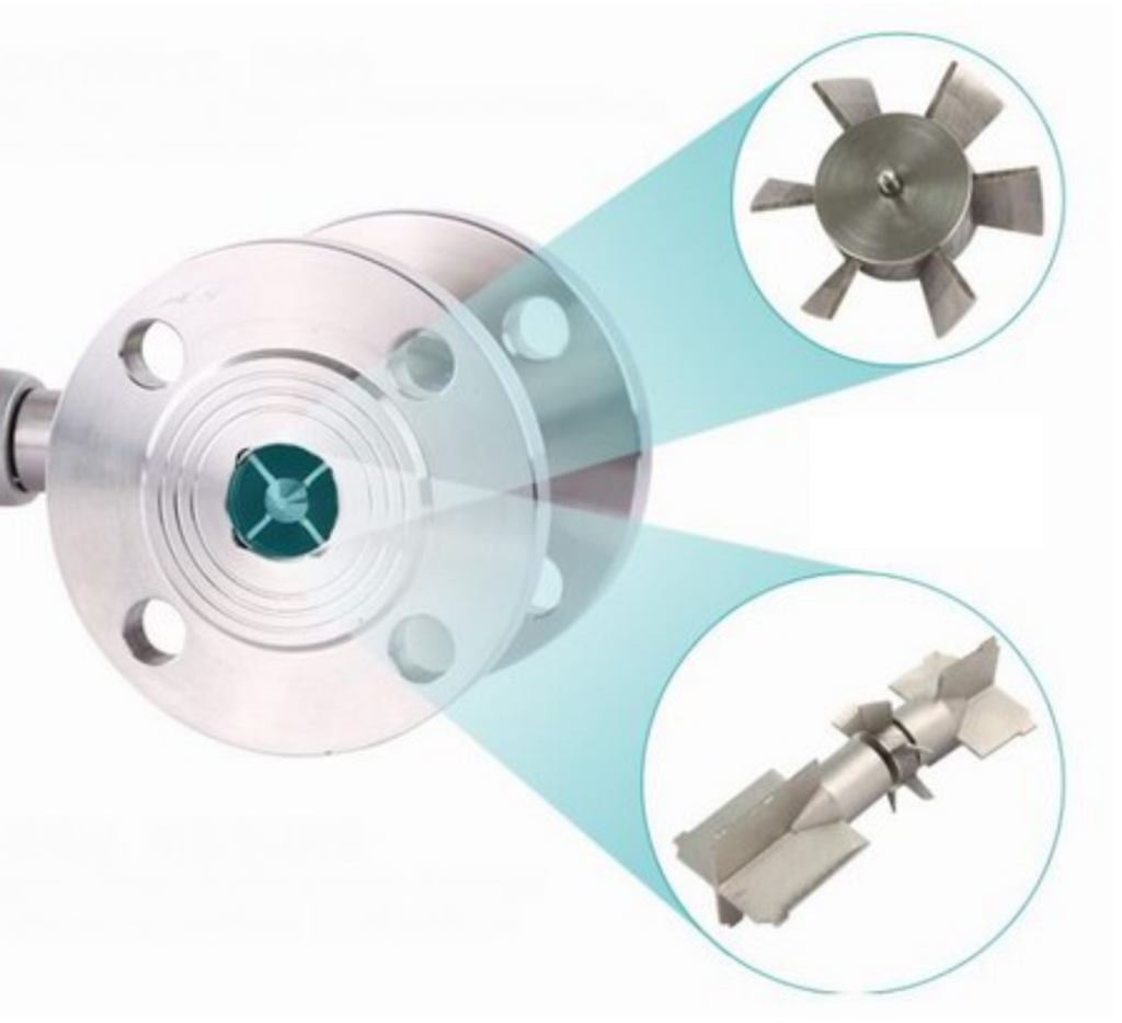
The mechanical part of a turbine flowmeter has a turbine rotor placed in the path of the flowing water flow.
The only moving part of a turbine flowmeter is the mechanical rotor. The rotational speed of the rotor depends on the flow rate. Rotor blades are usually made of stainless steel.
As the rotor rotates, an eddy current pulse is generated by each rotor blade passing through a blade pickup point.
Eddy current pulses are generated in different ways depending on the characteristics of the rotor blade itself and the blade pickup unit.
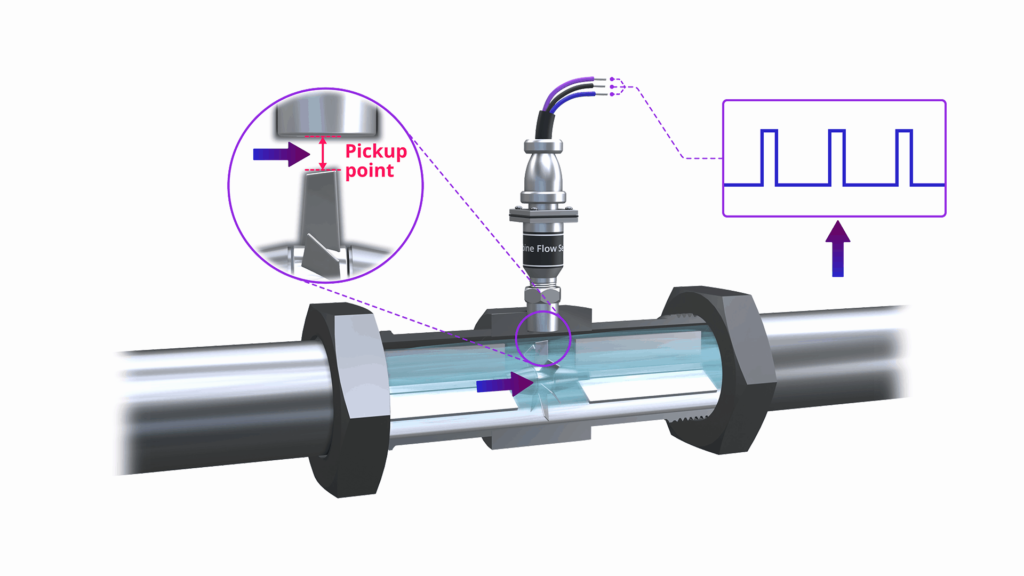
Eddy Current Magnetic Sensor
In most turbine flow meters, magnets are mounted on the vanes and magnetic eddy current pickup sensors are used to generate the pulses.
The higher the flow rate, the faster the rotor turns and the higher the number of pulses.
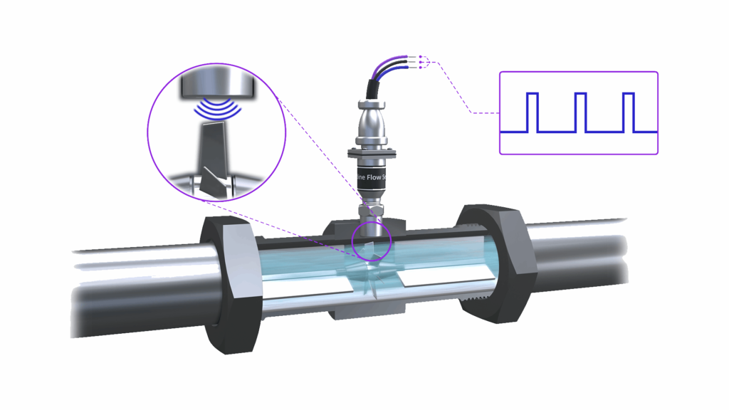
The shape and voltage levels of the generated pulses are entirely dependent on the type of eddy current pickup cell sensor used.
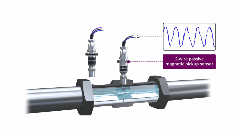
1) Electronic Eddy Current Pickup The sensing device can be a simple 2-wire DC magnetic eddy current pickup, producing an AC type output.
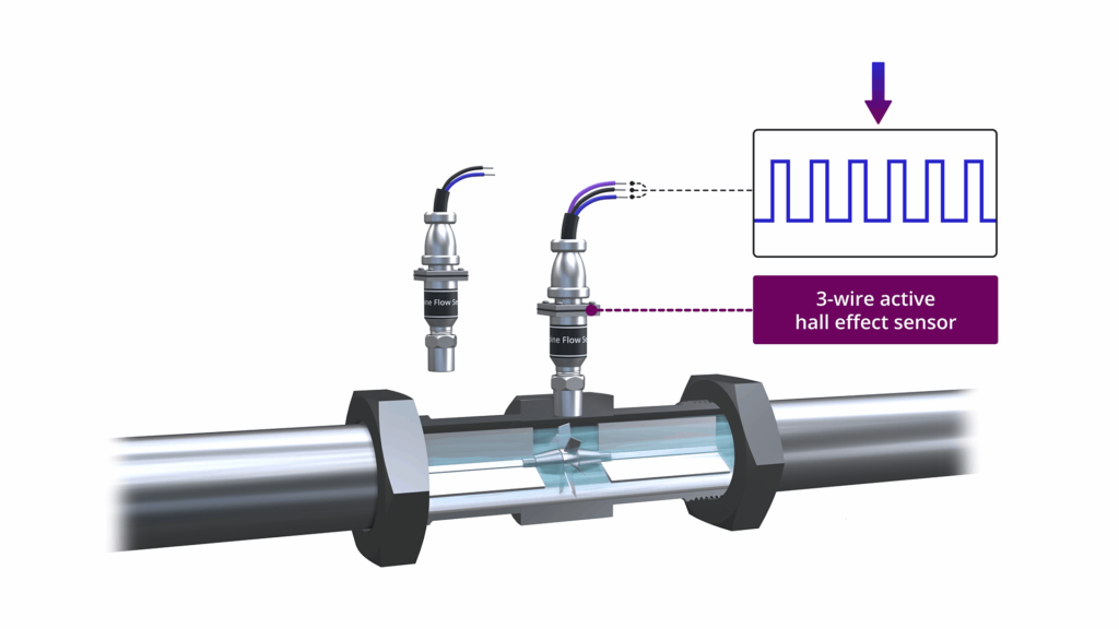
2) The eddy current pickup sensing device can be a 3-wire AC device, such as a Hall effect sensor, which produces a cleaner and more uniform square wave pulse.
Volume flow is the unit of flow
As we said before, the turbine rotor will turn at different speeds depending on the fluid flow rate.
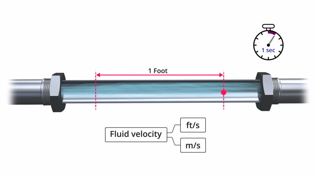
Fluid velocity is a measure of the distance traveled by particles of matter per unit of time. Typical speed units are feet/second or meters/second.
Fluid velocity plays a very important role in the operation of turbine flowmeters, but in most applications turbine flowmeters are used to measure volumetric flow.
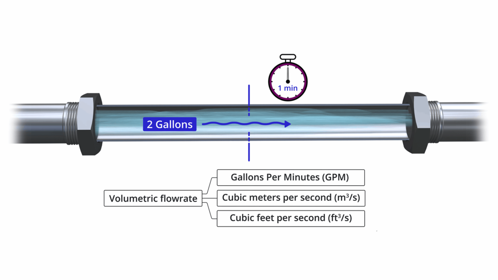
Volume flow refers to the volume of fluid passing through a certain point per unit time.
If you can calculate the number of gallons of liquid that flow through a certain point in one minute, you will be able to account for volumetric flow.
Volume flow is expressed in units, for example:
– Gallons per minute (GPM)
– cubic meters per second (m³/s)
– Cubic feet per second (ft³/s)
K factor
OK...so now that we've reviewed fluid velocity and volumetric flow, let's talk about how to measure volumetric flow using a turbine flowmeter.
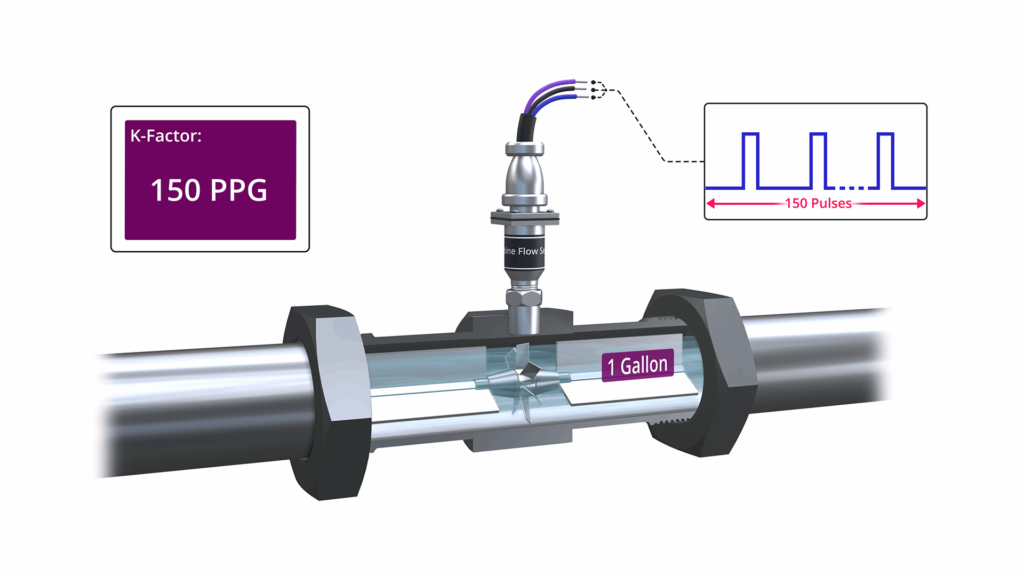
When you buy a turbine flowmeter, it should come with a label or certificate of calibration stating its K-factor.
This K-factor is unique to each turbine flowmeter and is given bymanufacturerSure.
As mentioned earlier, a turbine flow meter will generate pulses, the rate of which depends on the fluid velocity.
The unique K-factor declares the number of pulses each product unit passing through it will generate.
The K factor will be expressed in the number of pulses produced, eg 150 pulses per gallon.
Flowmeter Frequency Calculation
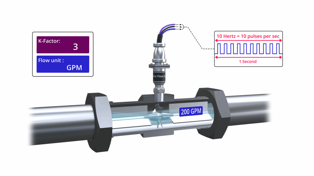
Suppose we are using a turbine flow meter to measure flow in gallons per minute (GPM).
The K-factor for this turbine flowmeter is 3 pulses per gallon.
Recall that frequency is measured in Hertz (HZ). 1 Hz is equal to 1 cycle per second.
With this in mind, we say that a turbine flowmeter produces a pulse rate per second, which we express in Hertz (HZ).
If we have a K-factor of 3 pulses per gallon, then the output frequency at a volume flow of 200 gallons per minute (GPM) is 10 Hz or 10 pulses per second.
If you're wondering where we got these values from, the manufacturer will generally provide a handy K-factor versus flow rate for you to use after correction.
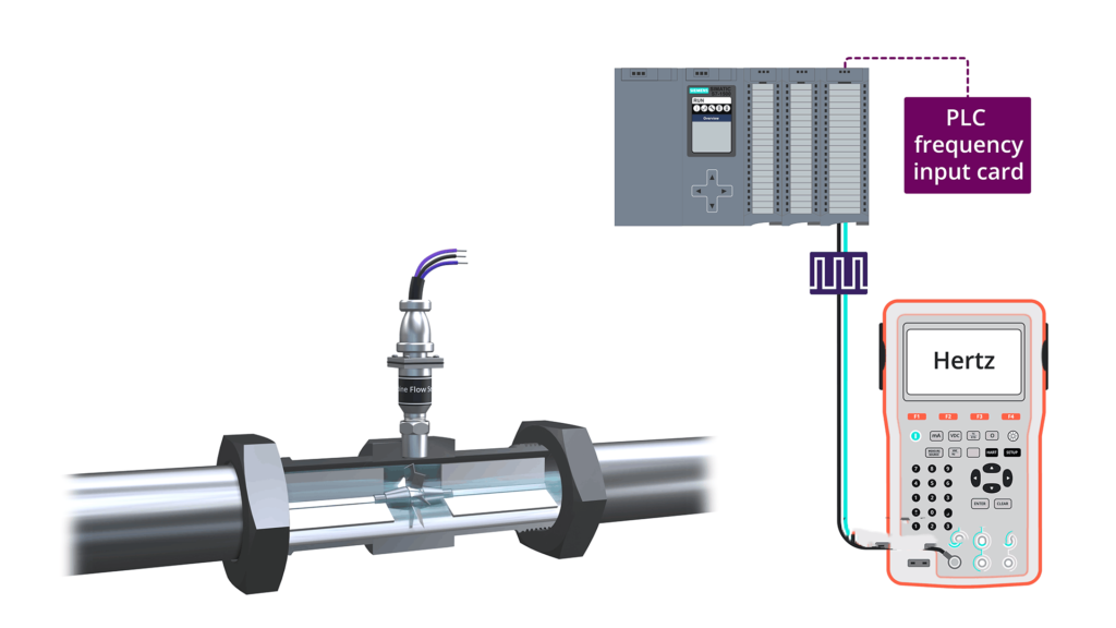
We can connect the turbine flowmeter to the PLC frequency input card. The input frequency now represents the volume flow.
If our PLC program is performing a loop calibration, we can use a calibrator with variable frequency output to simulate a turbine flowmeter.
Typical Field PLC Control Loop
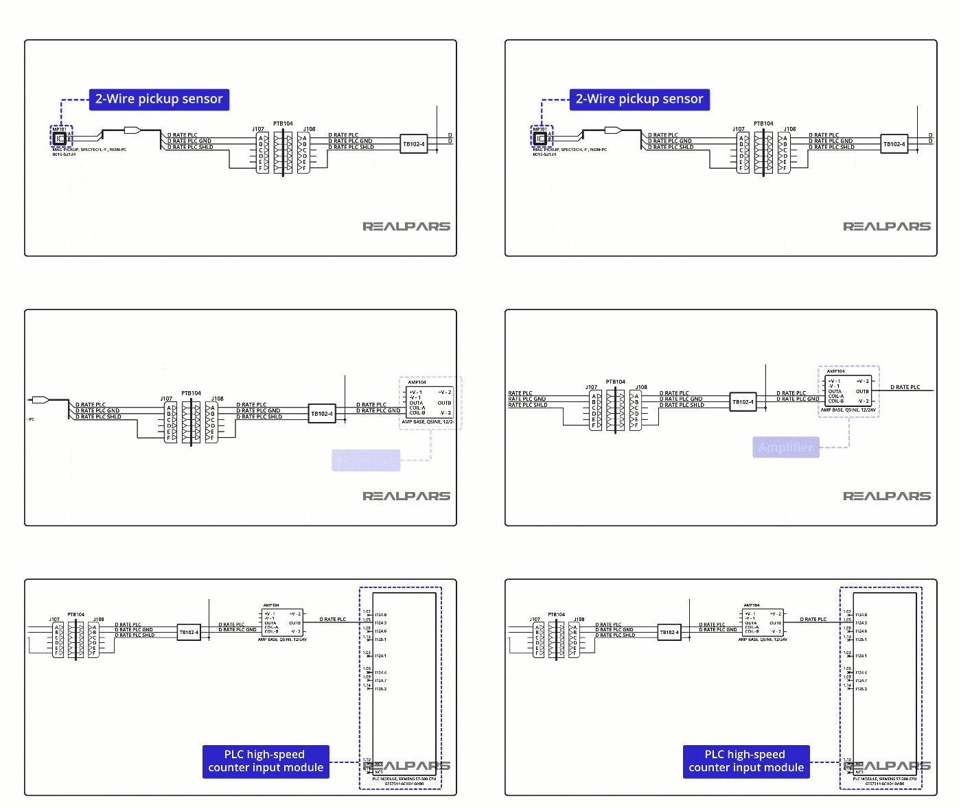
This is an example of a turbine volume flow measurement loop.
A 2-wire DC eddy current pickup unit generates AC-like pulses that are conditioned by an amplifier before being sent to the high-speed counter PLC input module.
Installation of Turbine Flow Meters
A typical installation requires 10 pipe diameters upstream and 5 pipe diameters downstream.
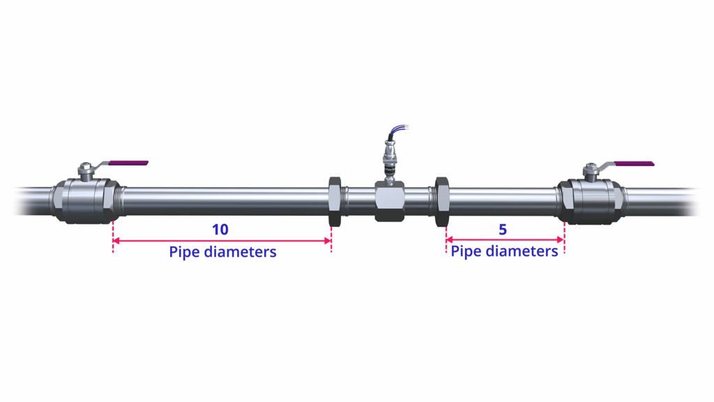
Turbine flow meters should only be used in clean lubricating fluids because suspended particles can easily damage the equipment.
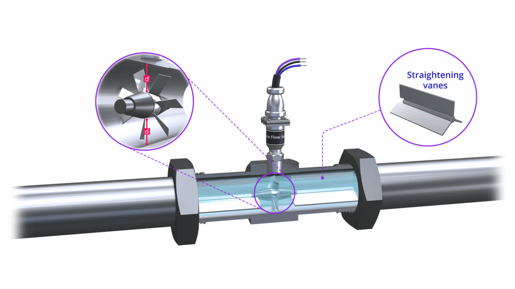
Turbine rotors must be at the precise center of the flow, and turbine rotor laminar flow accuracy is critical, often requiring straightened blades.
Disadvantages of Using Turbine Flow Meters
Although they are among the most accurate volumetric flow meters in use today, they do have some drawbacks.
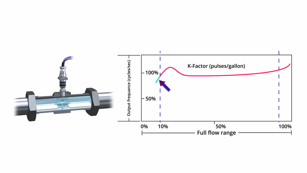
1) The K-factor is not always consistent over the entire flow measurement range. Turbine flow meters are not accurate at very low flow rates.
2) Viscosity is an issue as thicker or thinner fluids can change rotor speed and affect meter calibration.
Remember that the turbine flow meter K-factor is determined at the factory using a specific set of parameters.
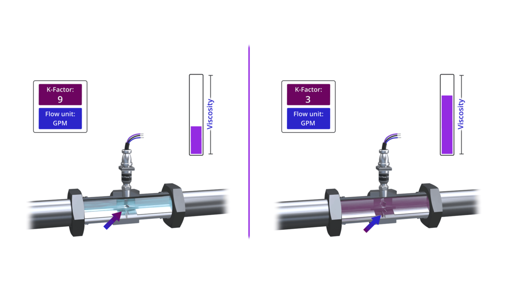
3) They are not recommended for use with steam. Like other mechanical equipment, rotor bearings wear out.
Where are turbine flow meters used?
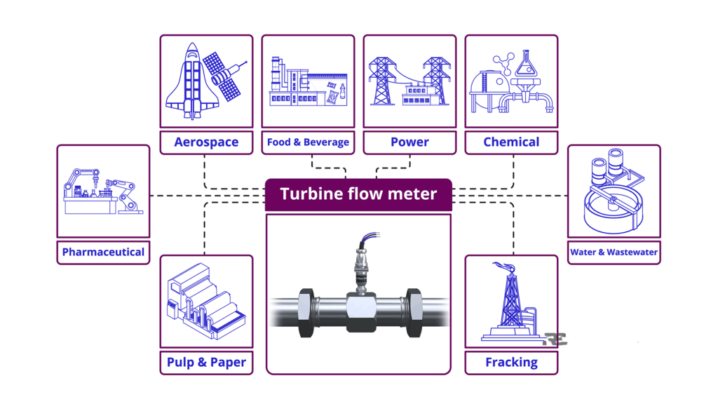
What industries are turbine flow meters used in? Given their popularity, a better question might be what industries are turbine flow meters not used in?
You'll find turbine flow meters in oil and gas, including hydraulic fracturing, water and wastewater, chemical, power, food and beverage, aerospace, pharmaceutical, and pulp and paper.
