FGT think your best choice in the future
System Integration Designers in FGT
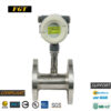
FRV-F Series | Turbine Flow Meter | Oil Flow Meter
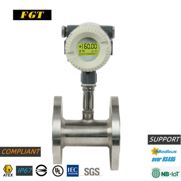
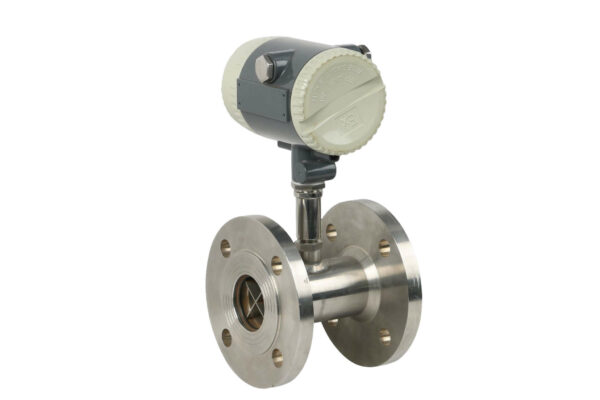
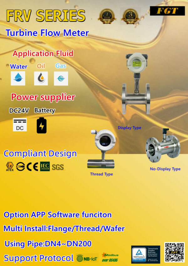
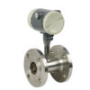
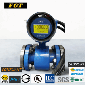
FRV turbine flowmeter: It adopts integrated molding and processing design. Applicable pipe diameter: DN4 ~ DN200. It can effectively improve the unstable measurement of small flow and large flow. It is developed by the first general design of FGT. Measurement: diesel, gasoline, methanol, water, weak acid , Weak alkali and other liquids have built-in electronically adjustable precision, the measured medium, no impurities, low viscosity, no strong corrosive liquid. In line with design standards ATEX, IEC1709, CE, SGS, BSMI and other international certification indicators design, output types: 4 ~20mA, Pulse, RS485, support MODBUS RTU, NB-IOT protocol, and can be used with SMM cloud software to realize remote meter reading monitoring
- Description
- Additional information
- Specification Table
- Size Chart
- Flow Range Table
- Ordering Information
- meet design standards
- Cloud monitoring function
- Special needs
- Inquire now
Product Features
characteristic
- High precision: standard ±1%R, optional ±0.5%R, high precision ±0.2%R.
- Repeatability from 0.05 R to 0.2 R,
- Output: Pulse (3 4 KHZ) frequency signal/4~20mA
- Wide range: medium and large pipe diameter 1:20, small pipe diameter 1:10
- Various connection methods: thread/flange/wafer
- Support protocol: NB-IOT/MODBUS RTU
- Power source: DC or battery
application:
- Boiler piping, air conditioning cooling systems and any delivery piping.
- Piping Requirement Installation Flow Application
- Existing Lines: Battery-Powered Design Immediately Know About Line Fluid Conditions
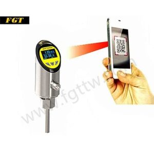
- On-site conditions, mobile phone monitoring settings
Featured Design
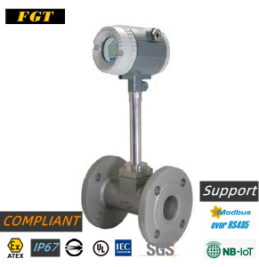
FRV vortex flowmeter: It adopts integrated molding processing design, applicable to pipe diameter: DN4 ~ DN200. It can effectively improve the unstable measurement of small flow and large flow. It is developed by the first general design of FGT. Measurement: diesel, gasoline, methanol, water, weak acid , Weak alkali and other liquids have built-in electronic adjustable accuracy, the measured medium, no impurities, low viscosity, no strong corrosive liquid. In line with design standards ATEX, IEC1709, CE, SGS, BSMI and other international certification indicators design, output types: 4 ~20mA, Pulse, RS485, support MODBUS RTU, NB-IOT protocol, and can be used with SMM cloud software to realize remote meter reading monitoring
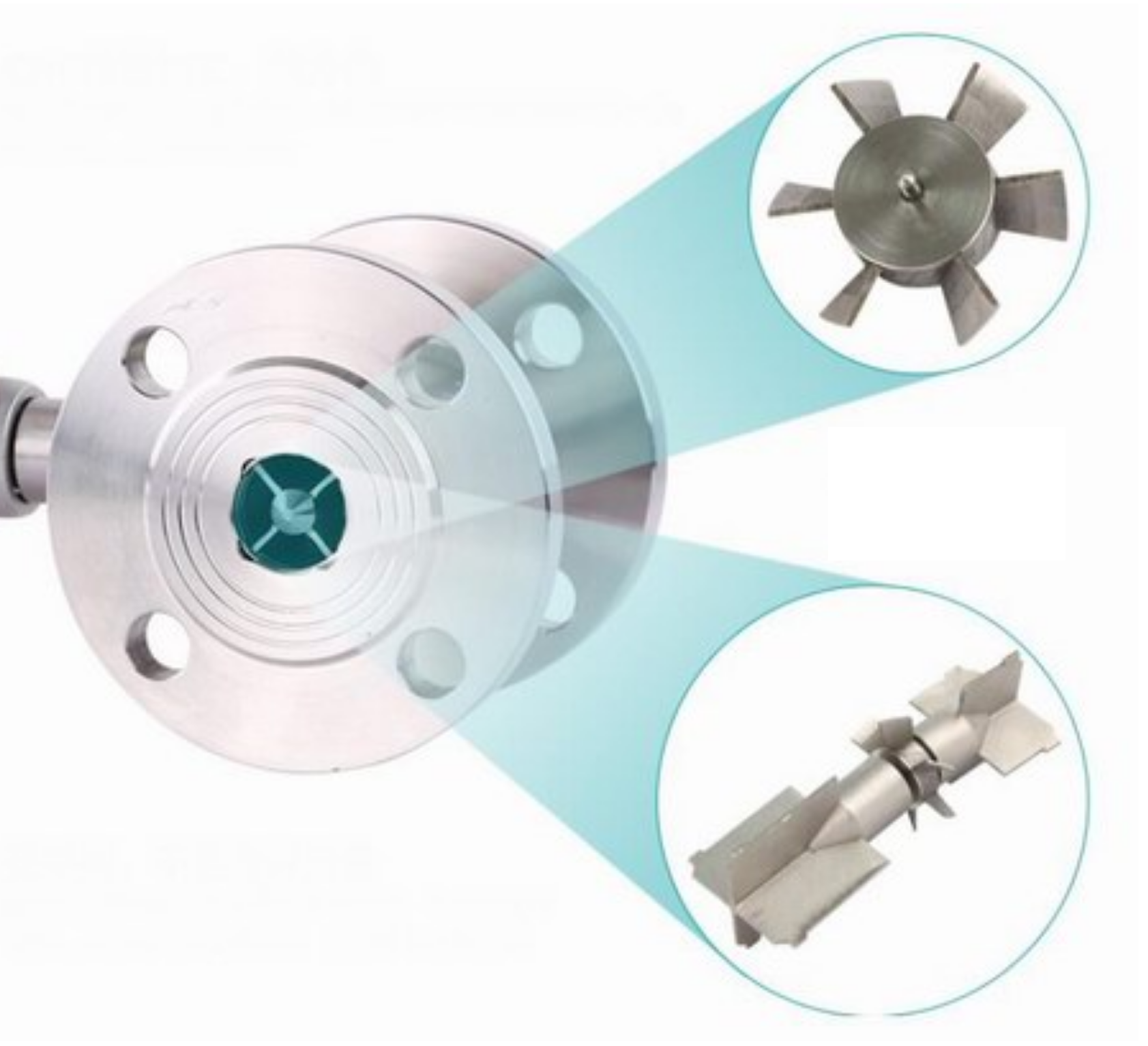
Blade core technology
Using non-magnetic stainless steel, one-time processing and molding, for micro-signal interference and adjusting the precision of the friction coefficient of the blade surface, effectively increase and reduce the blade speed and adjust the measurement coefficient
CNC integrated precision machining
Impact resistance - The blades of the turbine are processed in one piece without contact, which has strong impact resistance, more balance, real flow performance, and better dynamic balance of operation. At low flow rates, no idling value is generated, which is your precise check.
One-piece processing and molding
Streamlined guide bearing
Stainless steel bearings are selected, with stronger impact resistance, effectively reducing fluid pressure loss and avoiding measurement errors
Blades without solder joints
High-precision machining, the blade is arc-shaped
Universal Welded Blade|Ordinary Probe Steel Material Guide Bearing
Blade solder joints are prone to embrittlement and fracture
The blade is flat, and the smoothness cannot measure the small flow on the side.
Poor impact resistance, easy to wear, small and too poor shunt, causing interference to measurement
Computing Processor Design:
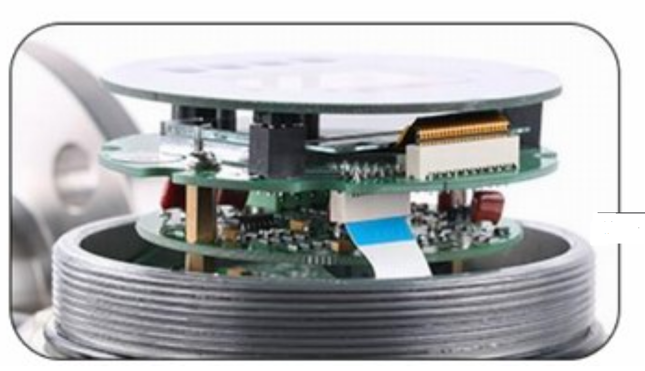
Adopt multi-layer module function board design, any damage to any function board can be replaced independently
Adopt communication socket connection design, strong and stable signal connection
Turbine Flow Meter | Working Principle
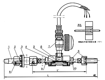
composition
Instrument structure
1. The instrument installation adopts flange connection, threaded connection and clip-on type;

| Control | IoT, PLC |
|---|---|
| Application | Flow Meter |
| Types of | Electronic |
| Installation method | Flange, Mouth, Pinch |
| Output method | digital, switch, analog |
Specification Table
| model | FRV-F | FRV-W | FRV-T |
| Dimensions (mm/Inch) | DN15~DN200 | DN4~DN100 | DN4~DN40 |
| Connection method | Flange | clip | Thread |
| precision | ±1.0% RD | ||
| ±0.5% RD | |||
| Optional: ±0.2% RD | |||
| Turndown ratio | 1:10;1:15;1:20 | ||
| Sensor material | SS304,SS316(L) | ||
| operating temperature | -20~+120℃(standard type) | ||
| ambient temperature | -20~+60℃ | ||
| Pressure resistance | 6.3Mpa(Max.) | ||
| Protection level | IP65 or higher (customizable) | ||
| Explosion-proof grade, Exd IIC T6Gb | |||
| monitor | 4-line LCD, 4-digit instantaneous flow, 8-digit cumulative flow | ||
| Current output | 4~20mA(2-wire)/600ohm | ||
| Pulse output | Pulse (3-wire) / Rating: 3~30Vdc, 20 mA max | ||
| Communication output | Modbus RTU RS-485 | ||
| Wifi Cloud | Zigbee Wifi to SMM Cloud Sensor Software | ||
| storage memory | EEPROM storage: operating parameters and accumulated data for more than 10 years | ||
| signal connection | 2 X M20*1.5 | ||
| Power supply mode #1 | A. External power supply: +24VDC±15%, ripple≤±5%, Suitable for 4~20mA output, pulse output, RS485, etc. |
||
| Power supply mode #2 | B. Battery power supply: 1 3.6V lithium battery, the battery voltage can be It works normally at 3.0V~3.6V. |
||
Size Chart
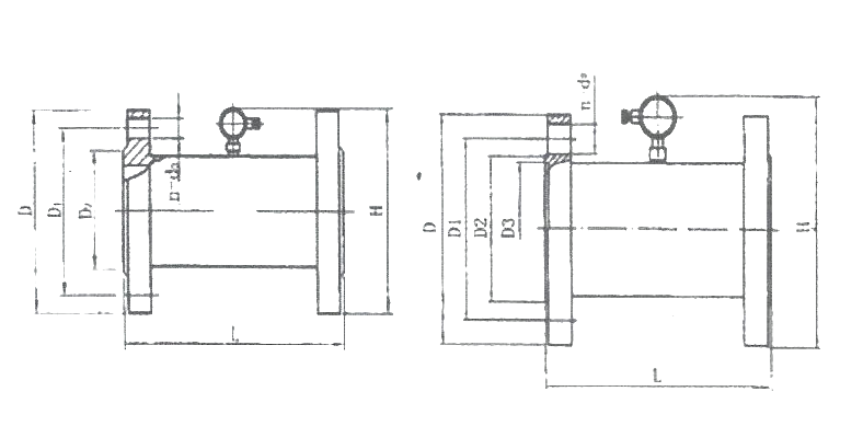
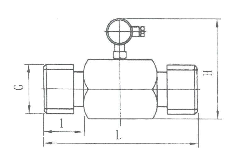
| size | Flange | Thread | ||||||||
| (mm) | Inch | L(mm) | H(mm) | D(mm) | D1(mm) | D2(mm) | D3(mm) | n-do | L1(mm) | G |
| 4 | ф4 | 1/2 | ||||||||
| 6 | ф6 | 1/2 | ||||||||
| 10 | 3/8″ | 1/2 | ||||||||
| 15 | 1/2″ | 75 | 190 | 95 | 65 | 46 | 4-14 | 23 | 1 | |
| 20 | 3/4″ | 85 | 210 | 105 | 75 | 56 | 4-14 | 23 | 1 | |
| 25 | 1″ | 100 | 230 | 115 | 85 | 65 | 4-14 | 30 | 11/4 | |
| 32 | 1-1/4″ | 110 | 250 | 140 | 100 | 76 | 4-18 | 30 | 11/4 | |
| 40 | 1-1/2″ | 140 | 260 | 150 | 110 | 84 | 4-18 | 35 | 2 | |
| 50 | 2″ | 150 | 270 | 160 | 125 | 100 | 4-18 | |||
| 150 | 275 | 175 | 135 | 105 | 55 | 4-23 | ||||
| 65 | 2-1/2″ | 150 | 290 | 185 | 145 | 125 | 76 | 4-18 | ||
| 80 | 3″ | 200 | 300 | 195 | 160 | 135 | 8-18 | |||
| 200 | 310 | 210 | 170 | 140 | 121 | 8-23 | ||||
| 100 | 4″ | 220 | 330 | 230 | 190 | 160 | 8-23 | |||
| 220 | 340 | 250 | 200 | 168 | 150 | 8-25 | ||||
| 125 | 5″ | 250 | 380 | 270 | 220 | 189 | ||||
| 250 | 390 | 280 | 240 | 200 | 170 | 8-30 | ||||
| 150 | 6″ | 300 | 390 | 300 | 250 | 218 | 8-25 | |||
| 300 | 410 | 340 | 280 | 240 | 204 | 8-34 | ||||
| 200 | 8″ | 360 | 455 | 360 | 310 | 278 | 12-25 | |||
| 360 | 470 | 405 | 345 | 300 | 260 | 12-34 | ||||
| 250 | 10″ | 400 | 510 | 425 | 370 | 332 | 12-30 | |||
| 300 | 12″ | 420 | 565 | 485 | 430 | 390 | 16-30 | |||
| 400 | 16″ | 560 | 680 | 610 | 550 | 505 | 16-34 | |||
| 500 | 18″ | 600 | 790 | 730 | 660 | 610 | 20-41 | |||
Flow Range Table
| size | normal flow range Accuracy ±0.5% |
Extended flow range Accuracy ±1.0% |
Connection Type and maximum pressure (Mpa) |
Special maximum pressure (Mpa) | initial flow (M3/Hr) |
| (mm) | M3/Hr | M3/Hr | |||
| 4 | 0.04~0.25 | 0.04~0.4 | Mouth/6.3Mpa | Clamping type <42Mpa | 0.02 |
| 6 | 0.1~0.6 | 0.06~0.6 | Mouth/6.3Mpa | 0.05 | |
| 10 | 0.2~1.2 | 0.15~1.5 | Mouth/6.3Mpa | 0.07 | |
| 15 | 0.6~6 | 0.4~8 | Mouth/6.3Mpa | 0.35 | |
| Flange/2.5Mpa | |||||
| 20 | 0.8~8 | 0.45~9 | Mouth/6.3Mpa | 0.3 | |
| 20 | Flange/2.5Mpa | ||||
| 25 | 1~10 | 0.5~10 | Mouth/6.3Mpa | 0.4 | |
| 25 | Flange/2.5Mpa | ||||
| 32 | 1.5~15 | 0.8~15 | Mouth/6.3Mpa | 0.6 | |
| 32 | Flange/2.5Mpa | ||||
| 40 | 2~20 | 1~20 | Mouth/6.3Mpa | 0.6 | |
| 40 | Flange/2.5Mpa | ||||
| 50 | 4~40 | 2~40 | Flange/2.5Mpa | Clamping type <26Mpa | 1 |
| 65 | 7~70 | 4~70 | Flange/2.5Mpa | 4 | |
| 80 | 10~100 | 5~100 | Flange/2.5Mpa | 5 | |
| 100 | 20~200 | 10~200 | Flange/1.6Mpa | Clamping type <15Mpa | 8 |
| 125 | 25~250 | 13~250 | Flange/1.6Mpa | 10 | |
| 150 | 30~300 | 15~300 | Flange/1.6Mpa | 12 |
Ordering Information
| Order model | |||||||||||||
|
coding | interface | |||||||||||
| F | Flange Type (Standard Type) | ||||||||||||
| W | Clamp Type | ||||||||||||
| T | Mouth type | ||||||||||||
|
|
coding | fluid type | |||||||||||
| O | Oil (standard type) | ||||||||||||
| W | water | ||||||||||||
| G | gas | ||||||||||||
| S | Special Fluids (Please explain this fluid specification to us) | ||||||||||||
|
|
coding | Take over size | |||||||||||
| XXXX | 15~200mm (for flange type) | ||||||||||||
| XXXX | 15~200mm (for clip-on type) | ||||||||||||
| XXXX | 4~40mm (for dental mouth type) | ||||||||||||
|
|
coding | Body material | |||||||||||
| 4 | SUS304 (standard type) | ||||||||||||
| 6 | SUS316(L) | ||||||||||||
|
|
coding | Precision type | |||||||||||
| 1 | ±0.5% | ||||||||||||
| 2 | ±1.0% | ||||||||||||
| 3 | ±0.2% (please explain this fluid specification to us, the production cycle is long) | ||||||||||||
|
|
coding | Display type | |||||||||||
| 1 | no display | ||||||||||||
| 2 | Live display | ||||||||||||
|
|
coding | Power supply type | |||||||||||
| 1 | 24V power supply, local display, 4~20mA output type | ||||||||||||
| 2 | 24V power supply, no local display, pulse output type | ||||||||||||
| 3 | Battery powered, local display, no output | ||||||||||||
| 4 | External power supply, local display, RS485/current/pulse output | ||||||||||||
|
|
coding | output signal | |||||||||||
| A | 4~20mA (standard type) | ||||||||||||
| P | pulse | ||||||||||||
| R | RS-485 | ||||||||||||
| M | RS485+4~20mA+pulse | ||||||||||||
| N | No output (battery type only) | ||||||||||||
|
Wifi | ||||||||||||
| coding | Protection level | ||||||||||||
| N | IP65 (standard) | ||||||||||||
| X | Explosion proof, Exd IIC T6 | ||||||||||||
|
|
coding | label | |||||||||||
| F | FGT | ||||||||||||
| N | Printing custom labels | ||||||||||||
|
|
|||||||||||||
| FRV | Complete order model | ||||||||||||
| *Note: All models support voltage (+12~24 Vdc) | |||||||||||||
meet design standards
meet design standards
- EX-ATEX
- IP67
- BSMI
- CE
- IEC
- SGS
Support communication protocol
- NB-IOT
- MODBUS-RTU
- ZIGBEE
Cloud monitoring function
Support SMM cloud monitoring
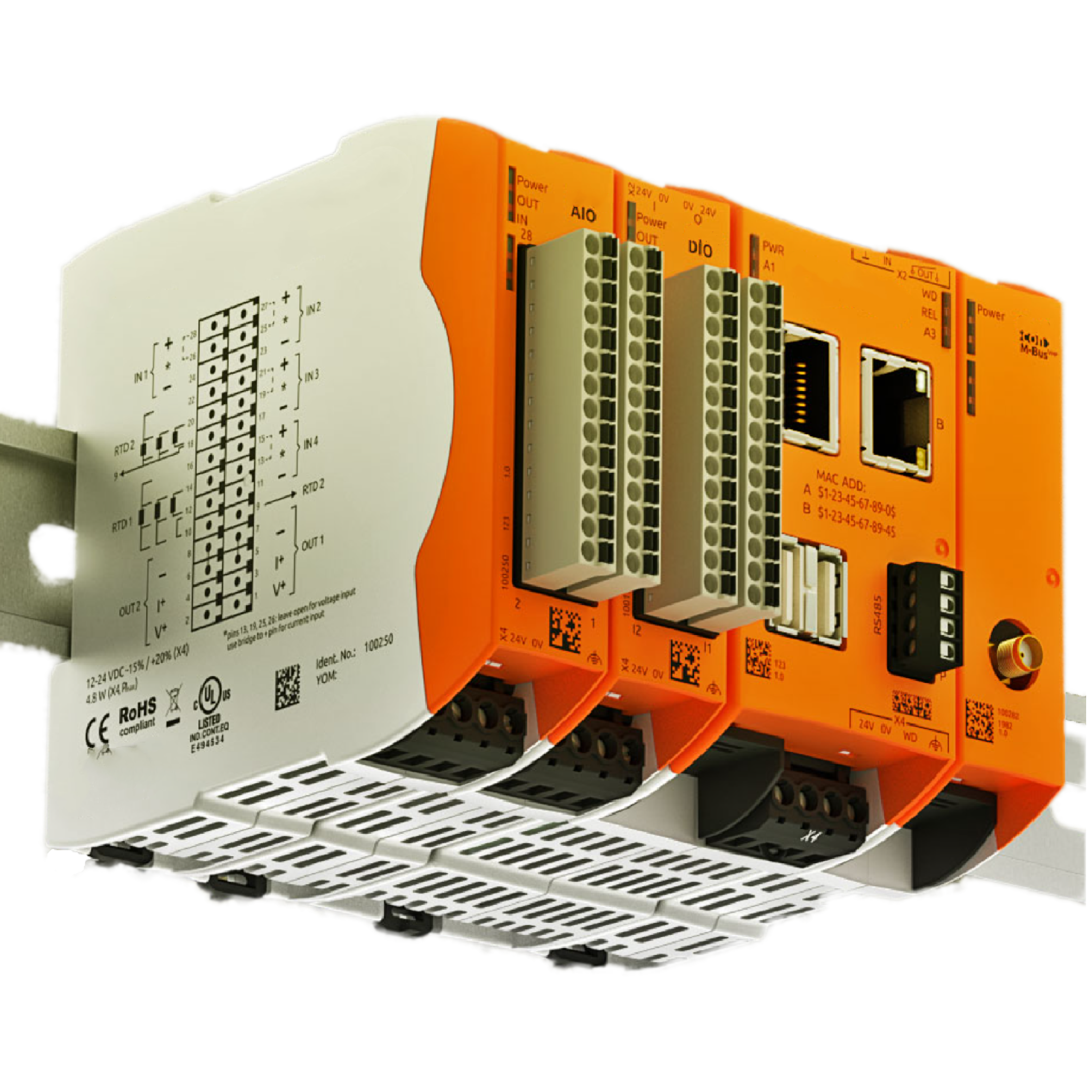
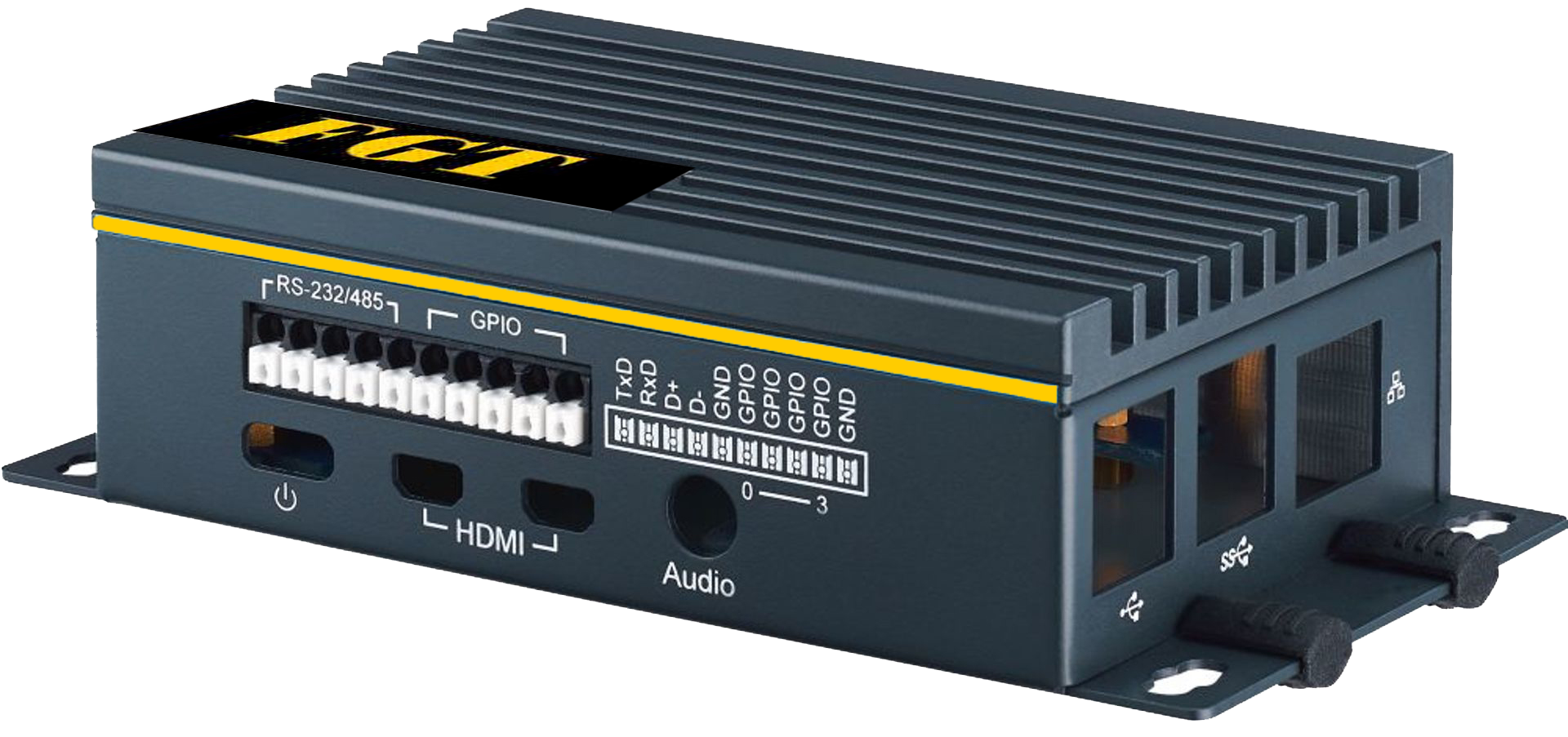
rail mount(optional model: IOT- D)
It can be integrated with the control panel for integrated installation, requiring power supply DC
Use plug and play physical RJ45 wiring
Stable and reliable signal quality
- Maximum support: 16 sets of RS485 sensors
- Expansion input module: AIO DIO
- wireless module
Economical installation(optional model: IOT- N)
It can be integrated with the control panel for integrated installation, requiring power supply DC
Use plug and play physical RJ45 wiring
- Maximum support: 16 sets of RS485 sensors
- Trend
- Device location settings
- Device location picture
- Free Settings: Alarm
- Statistics: Usage Units: Year/Month/Day

