FGT think your best choice in the future
System Integration Designers in FGT
Weak Current Diagram Symbols-Information Equipment Engineering Category-Smart Building Standard Symbols
I wonder if you have any experience with weak current system diagrams and symbols being inconsistent, resulting in poor communication between designers, constructors and related manufacturers? In order to solve this problem, the Construction Research Institute of the Ministry of the Interior has launched 752 standard symbol electronic diagrams, which are special weak current diagram symbols for smart building labels.
8.1. smart building. Standard symbols. 8.1.1 Insmart buildingWeak current system design drawing illustrates the use of smart buildingsStandard symbols. 3. All weak current system design drawings are used.smart buildingStandard symbol . can get 3 points
Classification of weak current diagram symbols
1.Information equipment engineering (weak current diagram symbols)
Box type
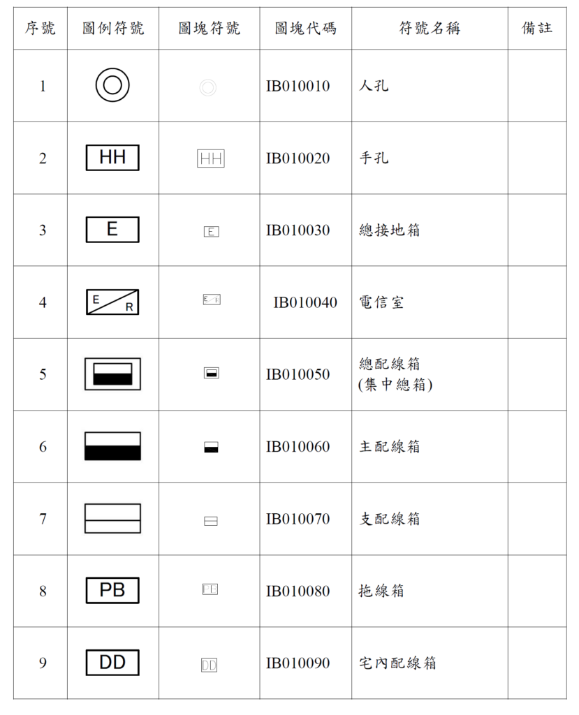
Instructions for using the main weak current diagram symbols
Manhole: A maintenance hole set up in a building for maintenance personnel to enter before the five major pipelines outside the building line are introduced into the building.
Hand hole: Set up in a building where the five main pipelines and weak current pipelines enter the building and can be operated and maintained by maintenance personnel's hands.
Main grounding box: The main grounding box should be installed near the main wiring box on the first floor or in an appropriate location in the lowest basement. buried underground
The ground electrode is connected to the box through a ground wire.
Telecommunications room: refers to a special space in a building for local network business operators to connect cables and install telecommunications equipment.
Wiring box
(1) Wiring boxes are classified according to their functions, including the following categories:
Main wiring box
Centralized main box
Main wiring box
Distribution line box
Trailer box
Indoor wiring box
(2) Various wiring boxes in the building are used for the direct passage of cables, or for the storage of cable connections and terminals. All cables that are jumpered in the box must be terminated. The correct type of splicing hardware must be installed in the box to match the cable type for cable termination, such as indoor composite terminal boards, terminal boards, telephone socket sets, information The specifications of socket sets, optical cable distribution boxes, optical cable distribution boxes, etc. shall comply with the relevant technical specifications set by the Association.
(3) The grounding terminal board and its grounding equipment should be installed at an appropriate location in the box.
(4) Relevant cable distribution information should be attached to the appropriate location of the wiring box.
(5) Equipment or lines other than telecommunications cables and equipment shall not be accommodated in the wiring box. However, this does not apply if the space of the wiring box in the house is sufficient to accommodate other equipment or lines other than telecommunications cables and equipment.
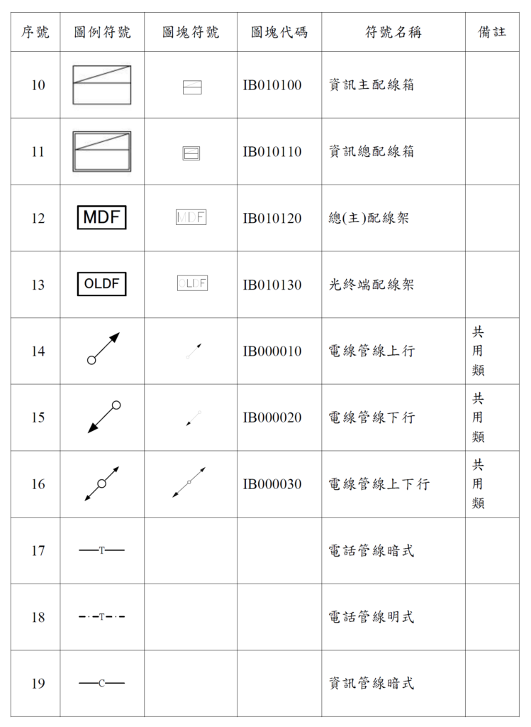
Instructions for using the main weak current diagram symbols
MDF: Main Distribution Frame,MDF):. Installed in buildingstelecommunicationsThe indoor metal combination frame serves as the interface between the introduction pipeline and the main pipeline
OLDF:Optical terminal distribution frame(Optical Line Distribution Frame, OLDF/ODF) A metal cabinet installed in the telecommunications room of a building, used for installing incoming optical cables, optical terminal boxes (boxes), optical splitters and optical terminal equipment
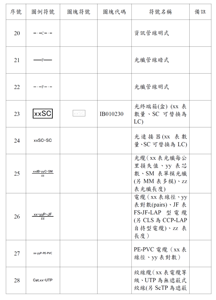
Instructions for using the live symbol
Optical terminal box (box) xxSC: configurationRefers to a splicing device that accommodates fiber optic connections or is a socket for multiple fiber optic connectors., can be installed in the main distribution box, centralized main box, main distribution box, distribution distribution box, house distribution box or other boxes, used as optical cable terminal connection and storage, providing optical cables, optical fiber leads and jumpers. Connect the three connections
Information pipeline and fiber optic pipeline symbols:
C: stands for information management, which is abbreviated from the English word communication.
F: stands for fiber optic tube, which is abbreviated from the English word Fiber.
Dotted line: represents the pipe, that is, the pipe that can be seen from the outside leakage
Solid line: represents hidden pipes, i.e. invisible pipes inside the building wall
SM: single mode fiber
MM: Multimode optical fiber
Cat.6-UTP:
Commonly known as network cables (Cat5, Cat6, Cat 6A, Cat7, Cat8, etc.), there is a cross isolation, which consists of a skeleton and 8-core wires. The 8-core wires are all twisted in pairs, with a total of 4 pairs of wires, and a A cotton rope is used for pulling skin. There is also an outer quilt. Generally, we use PVC for the outer quilt. There are many kinds of materials for the outer quilt. For example, there are also ones for outdoor use, which are the so-called PE outer quilts, which can resist UV sun protection and waterproof. The structure is basically the same inside. , UTP is unobstructed
Twisted wire (ScTP is shielded)
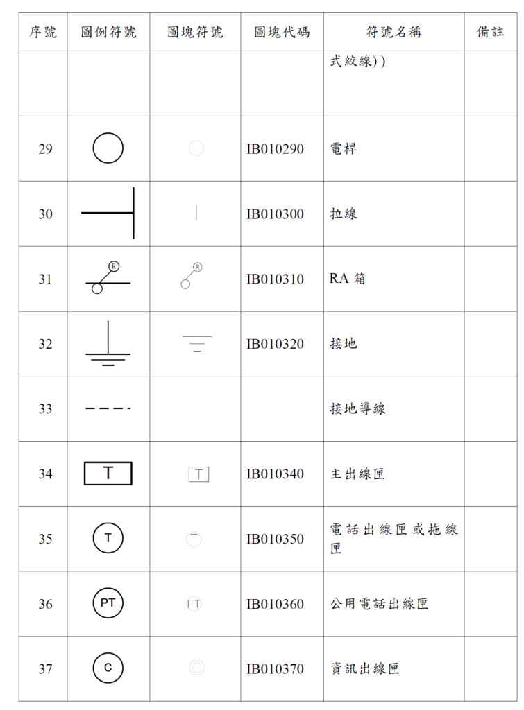
Main symbols usage instructions
Main outlet box:Refers to the outlet hole for installing telecommunications equipment in a building, which is a box-type device that can be used to install telecommunications sockets.
T: Telephone outlet box is abbreviated from the English abbreviation Telephone
C: Information outlet box: stands for information outlet box, which is abbreviated from the English abbreviation of communication.
PT: Public telephone outlet box stands for public telephone outlet box, which is abbreviated from the first two words of English public phone.
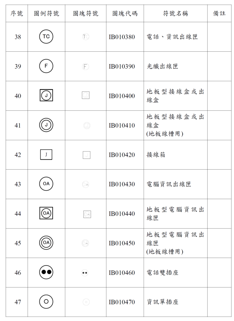
Main symbols usage instructions
TC: Telephone and information outlet box: represents a wall opening with these two pipelines
F: Optical fiber outlet box: the optical fiber terminal outlet after the main backbone of the building extends to the horizontal branch
J: Wiring symbols: There are many types of symbols, please refer to the picture above to understand
OA: Computer information outlet box: abbreviated from the first two letters of English Office Automation
Pig Nose: Dual telephone sockets, two sets of telephone lines on one wall
One hole: Information single socket, one wall equipped with Cat5, 6, 7, 8 network plugs
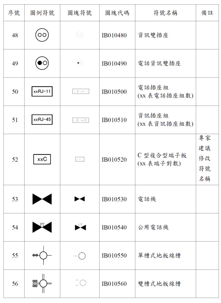
Main symbols usage instructions
Two holes: double information sockets, equipped with two sets of network cable sockets
Black and White Hole: Telephone Information Dual Socket: Configure a telephone and network line socket set
xxRJ-11: Telephone socket group, xx can represent several groups, this symbol is usually marked on the pull cord
xxRJ-45: Information socket group, xx represents several groups, this symbol is usually marked on the pull wire
xxC: Composite terminal board (C type) Each 10 pairs are used for cable connection, and the terminal blocks can be isolated. C-type terminal boards are generally used at the office line end. The terminal board itself is designed with wire slots to facilitate neat wiring of jumpers and facilitate maintenance. It has the function of snapping on the nameplate and dust cover, and comes with color code management to facilitate construction and maintenance.
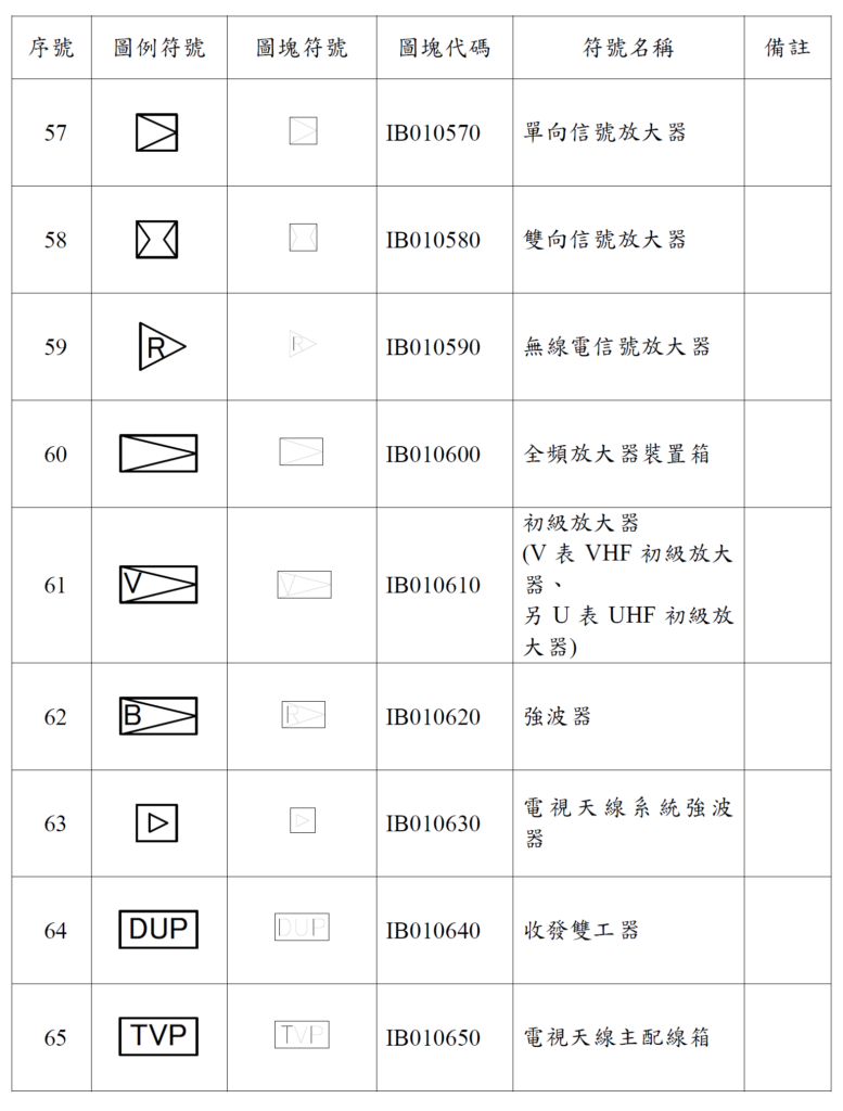
Main symbols usage instructions
Triangle: symbol for television signal amplifiers
V stands for VHF primary amplifier
U stands for UHF primary amplifier
B stands for wave booster
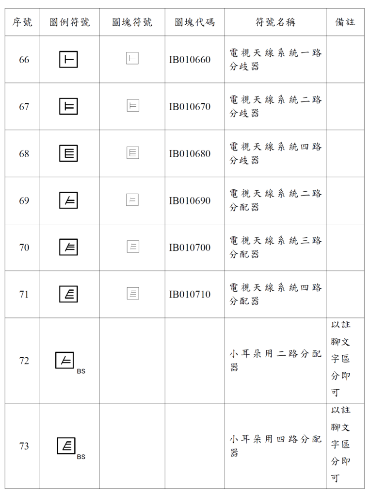
Instructions for use
A horizontal line: allocate all the waydevice
Two horizontal lines: two-way distributor
Three horizontal lines: three-way distributor
Slash plus horizontal bar: backbone shared antenna symbol
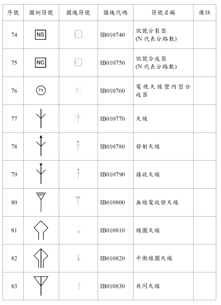
Main symbols usage instructions
TV: shared antenna outlet
Shared antenna: refers toReceive television signals from wireless television stations directly or indirectly from space, and transmit them to the receiving user's equipment using wired coaxial cables
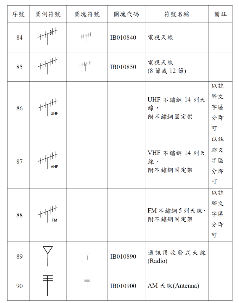
Instructions for use
UHF: Taiwan calls ultra high frequency, which refers toElectromagnetic waves with frequencies from 300MHz to 3GHz. Wavelengths range from 10cm to 1m. For short-distance communications, small and short antennas can be used for sending and receiving, and are suitable for mobile communications.
VHF:The frequency range is 30M to 300M, and its wavelength range is 1 meter to 10 meters, so this band is also called the meter wave band and the ultra-short wave band. Meter-wave radar has a smaller antenna and could be installed on ships during World War II to be used as a search/warning/early warning radar; this band makes it difficult for aircraft to become invisible.
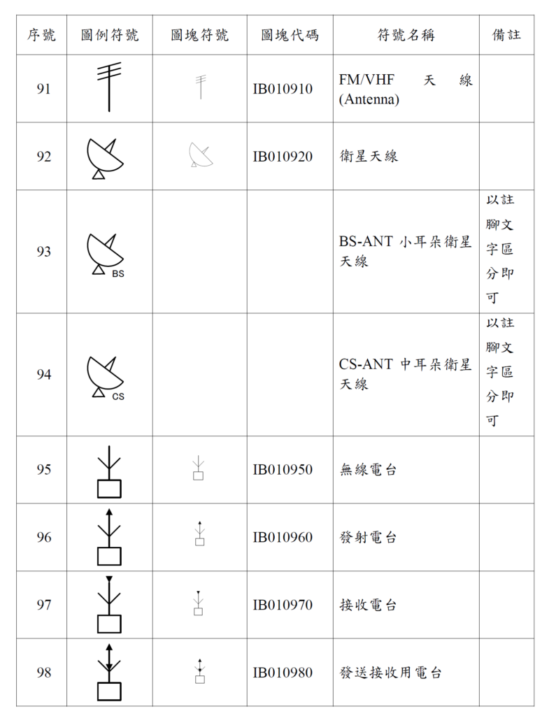
Main symbols usage instructions
This type is rarely used in the design of weak current diagrams for smart buildings.

Main symbols usage instructions
MODE: Modem refers to a MOD similar to that of Chunghwa Telecom. It is mainly set up at the household end and entrusts telecommunications or broadband telecommunications companies to install it. In the design of the weak current diagram of the building, it does not belong to the construction standards and needs to be designed on the drawing.