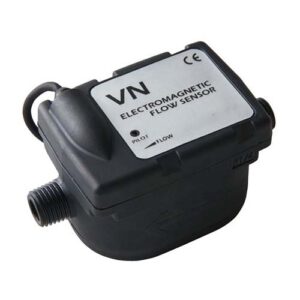
FGT think your best choice in the future
System Integration Designers in FGT
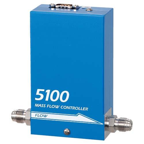
High-precision metal sealed mass flow controller Model 5100 series | kofloc brand
The 5100 series mass flow controller/instrument of Japan's kofloc manufacturer has the basic performance conditions required for semiconductor process control such as weldless structure, metal seal, accuracy ≤±1%, response ≤±1 second, and has achieved significant price reductions.・Weldless structure and metal seal achieve low leakage rate.・The dead volume is reduced due to the diaphragm seat valve.・The face-to-face and body dimensions and wiring connection points are designed to facilitate replacement of equipment manufactured by other companies.・The flow sensor with temperature following current difference detection achieves high accuracy and high response.
・A normally closed solenoid valve is used.
The kofloc brand 5100 series mass flow controller/instrument has the basic performance conditions required for semiconductor process control such as weldless structure, metal seal, accuracy ≤±1%, response ≤±1 second, and has achieved significant price reductions.
feature
・The flow sensor with temperature-following current difference detection realizes high precision and high response.
・A normally closed solenoid valve is used.
・Weldless construction and metal seals achieve low leakage rates.
・ Dead volume is reduced due to the diaphragm seat valve.
・ Face-to-face and body dimensions and wiring connection points are designed to facilitate replacement of equipment made by other companies.
Standard Specifications
! ! Remark! !
Specifications related to flow range (eg, flow range, accuracy, and response) are expressed in N2 or air equivalent. The product will be built with a primary pressure of 300 kPa or less and the secondary side open to atmosphere. Please contact us for details on pressure requirements.
Applications
・Air sampling
・Analyzer parts
·Bioreactor
・Biotechnology process
・Combustion control
・Made in CCFL
・Room pressure control
・Chemical process
・Environmental monitoring
・Manufacture of electronic equipment
・Food production
・Fuel cell test
・Fermentation process
・Gas mixing
・Gas distribution
・Airflow monitoring
·Gas generation
·Industrial furnace
·Leak detection
·Pharmaceutical process
·Pollution monitoring
·Process control
·R&D
·Solar cell manufacturing
· Secondary calibration reference
・Semiconductor process
・Surface treatment process
・Thermal flame spraying
・Film manufacturing
・Vapor deposition
What types of mass flow controllers exist?
Thermal mass flow controllers use the thermal mass sensing technique of gases to control their mass flow. In the TMFC portfolio we have several thermal mass flow controllers, each with its own sensor technology:
Mass flow controllers using bypass sensors. These devices, such as TMFCs and TMFMs, are ideal for clean and dry gas applications where greater precision and repeatability are required.
Mass flow controller using the on-line principle. Series such as the TMFC and TMFM series are perfect if your application has high purity gases above 99.9%, or when high repeatability and robustness are more important than accuracy.
Gas mass flow controller using piping control technology. These series stand out because they can measure gas flow and control.
Whenever your mass flow needs to be displayed and over a wide flow range, a gas series using MEMS chip sensor technology such as the TMFM6000 is perfect.
Gas mass flow controllers using in-line (CMOS) technology.
Mass Flow Controller ( MFC ) Principle / Flow Controller Principle
A mass flow controller (MFC) is a device used to measure and control the flow of liquids and gases. [1] Mass flow controllers are designed and calibrated to control a specific type of liquid or gas over a specific flow range. The MFC can have a set point between 0% and 100% of its full scale range, but typically operates within the full scale range of 10% to 90% for best accuracy. The device will then control the flow rate to the given set point. MFCs can be analog or digital. Digital flow controllers are usually capable of controlling more than one fluid, while analog controllers are limited to the fluids they are calibrated for.
All mass flow controllers have an inlet port, an outlet port, a mass flow sensor, and a proportional control valve. The MFC is equipped with a closed loop control system where the operator (or external circuit/computer) provides an input signal which is compared with the value of the mass flow sensor and adjusts the proportional valve accordingly to achieve the desired flow. Flow is specified as a percentage of its calibrated full scale flow and is provided to the MFC as a voltage signal.
Mass flow controllers require the supply gas or liquid to be within a specific pressure range. Low pressure will deplete the MFC of fluid and prevent it from reaching its set point. High pressures may cause erratic flow rates. There are many different technologies that help measure the flow of fluids and ultimately help control flow. These technologies define the types of mass flow controllers and they include differential pressure (ΔP), differential temperature (ΔT), Coriolis force, ultrasonic, electromagnetic, turbine, etc.

Mass Flow Meter Installation
Now there are more and more applications of mass flowmeters, and some occasions where mass flowmeters are installed for the first time are not clear about the installation method of mass flowmeters, reverse installation, wrong installation, etc., which affect the normal use of the equipment. This article discusses this problem Describe in detail how to install a mass flow meter.
Excessive mechanical stress during sensor installation will affect the zero point of the mass flowmeter. If these stresses are constantly changing, the zero point drift of the meter will cause inaccurate measurement and cannot work normally. Therefore, the correct installation of the mass flowmeter is an important part of ensuring the normal operation of the equipment.
1. Choose the installation method
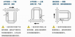
The installation method of the sensor is mainly determined according to the phase difference of the fluid and its process conditions. There are three installation methods.
1. If the measured fluid is a liquid, the sensor is generally installed with the shell facing down to avoid air accumulation in the vibrating tube of the sensor, so as to achieve the purpose of accurately measuring the mass flow rate.
2. If the measured fluid is gas, the sensor is generally installed with the shell facing upwards to avoid accumulation of condensate in the sensor vibration tube.
3. If the measured fluid is a mixed slurry of liquid and solid, install the sensor on a vertical official road, which can prevent particles from accumulating in the sensor's Coriolis force measuring tube. In addition, if the process pipeline needs to be cleaned with gas and steam, this installation method can also facilitate cleaning, but this installation method is more difficult to fix than the previous two, and the pressure loss is larger.
gas flow controller
gas mass flow controllers
Mass Flow Formula
Types of mass flow meters
mass flow meter english
according toThree degrees Chinese website.Multiple interpretations mass flowmeter【electronic computer term】mass flow meter【mechanical engineering】mass flowmeter sensor【marine science term-underwater engineering】thermal mass flow【electronic engineering】mass flow measurement【electrical engineering】
What is the use of electromagnetic flowmeter? | Our performance
What is a mass flow meter used for? | Our performance
What is the use of vortex flowmeter? | Our performance
What is the use of ultrasonic flowmeter? | Our performance
What is a gear flow meter used for? | Our performance
What is a float flow meter used for? | Our performance

