FGT think your best choice in the future
System Integration Designers in FGT
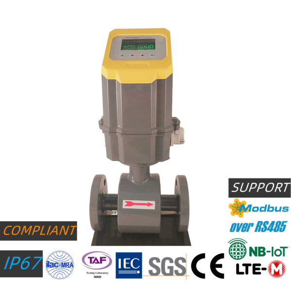
FMG-E type: integrated electromagnetic flowmeter | water flowmeter
FMG-E series: Applicable pipe diameter: DN15~DN2200 electromagnetic flowmeter,Electromagnetic FlowmeterFlow is detected using Faraday's law of induction. existElectromagnetic FlowmeterInside there is an electromagnetic coil that generates a magnetic field, and electrodes that capture the electromotive force (voltage)
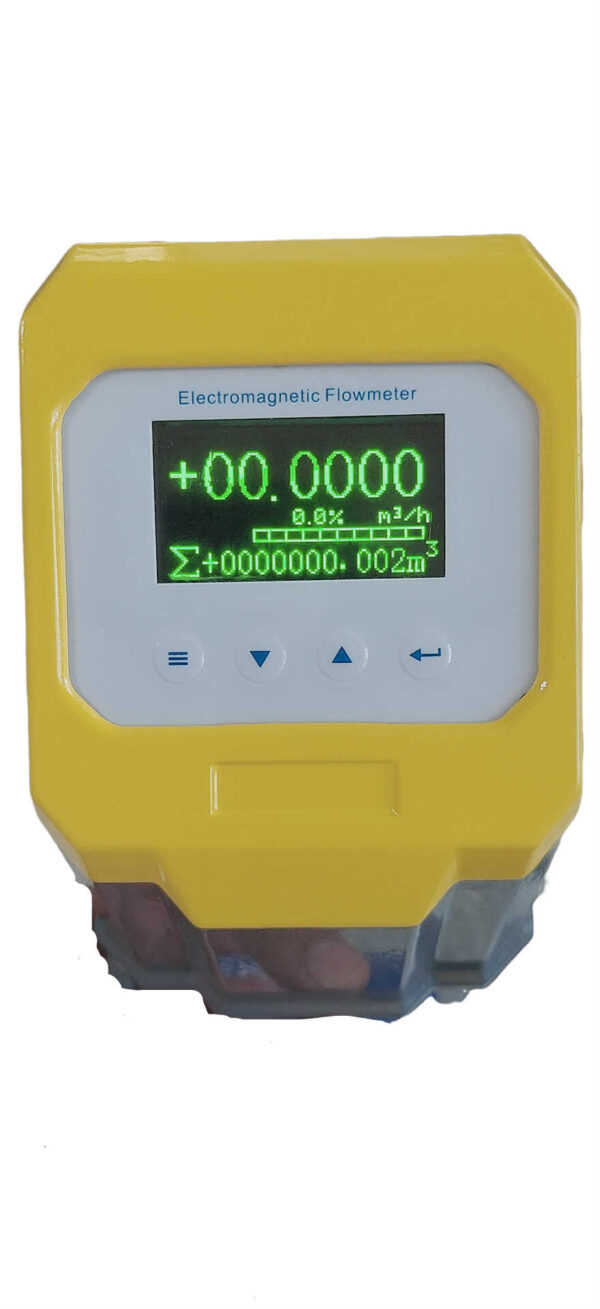
FMG-E series adopts intelligent OLED display function. Dual-language design. Display panel language: English/Traditional Chinese bilingual switch. Simple installation operation and can be installed vertically. Multiple size ranges to choose from. High accuracy: ±0.5% RD, anti-interference and no pressure loss. Multiple outputs: 4~20mA/pulse/MODBUS RTU.FGT first universal design meets standards: EX/IP67/IEC/SGS/ilac-mar/taf
- Description
- Additional information
- Technical Specifications
- Flow range
- Size Chart
- Application field
- Order model
- meet design standards
- IoT software
- certified
- Special needs
- Inquire now
- Smart OLED display function.
- Display panel language: English/Traditional Chinese bilingual switch
- Simple setup and installation.
- Various size ranges to choose from.
- Multiple outputs: 4~20mA/pulse/MODBUS RTU
- High precision: ±0.5% RD
- Anti-interference and no pressure loss.
- Comply with design standards: EX/IP67/UL/IEC/SGS/ilac-MAR/TAF
/Introduction to the principle of electromagnetic flowmeter/
Electromagnetic Flowmeters (EMF for short) is a new type of flow measuring instrument developed rapidly with the development of electronic technology in the 1950s and 1960s. Electromagnetic flowmeter is an instrument that uses the principle of electromagnetic induction to measure the flow of conductive fluid according to the electromotive force induced by the conductive fluid passing through an external magnetic field.
The principle of electromagnetic flowmeter is based on Faraday's law of electromagnetic induction. When the conductor moves in the magnetic field to cut the magnetic field lines, an induced potential will be generated in the conductor, and the magnitude of the induced potential is proportional to the effective length of the conductor in the magnetic field and the speed of the conductor in the magnetic field perpendicular to the direction of the magnetic field. In the same way, when the conductive fluid flows in the vertical direction in the magnetic field and cuts the magnetic induction line, an induced potential will also be generated on the electrodes on both sides of the pipe.
The volume flow rate is equal to the product of the fluid velocity v and the pipe cross-sectional area (πD²)/4. When the pipe diameter D is fixed and the magnetic induction intensity B is kept constant, the measured volume flow rate has a linear relationship with the induced potential. If an electrode is inserted on both sides of the pipe, an induced potential can be introduced, and the volume flow can be obtained by measuring the magnitude of this potential.
1. Structure of electromagnetic flowmeter
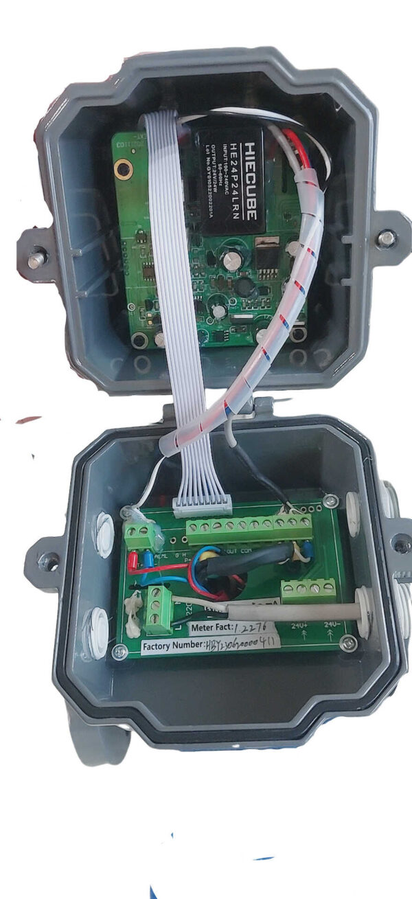
The structure of electromagnetic flowmeter is mainly composed of magnetic circuit system, measuring conduit, electrode, shell, lining and converter.
1. Magnetic circuit system: its function is to generate a uniform DC or AC magnetic field. The DC magnetic circuit is realized by a permanent magnet, which has the advantages of simple structure and less interference by the AC magnetic field, but it is easy to polarize the electrolyte liquid in the measuring catheter, so that the positive electrode is surrounded by negative ions, and the negative electrode is surrounded by positive ions. Surrounding, that is, the polarization phenomenon of the electrodes, and leads to an increase in the internal resistance between the two electrodes, thus seriously affecting the normal operation of the instrument. When the diameter of the pipeline is large, the permanent magnet is correspondingly large, cumbersome and uneconomical, so the electromagnetic flowmeter generally adopts an alternating magnetic field, and is generated by the excitation of a 50HZ power frequency power supply.
2. Lining: There is a complete electrical insulating lining on the inner side of the measuring conduit and the sealing surface of the flange. It directly contacts the liquid to be measured, and its function is to increase the corrosion resistance of the measuring conduit and prevent the induced potential from being short-circuited by the wall of the metal measuring conduit. Lining materials are mostly corrosion-resistant, high-temperature-resistant, wear-resistant PTFE plastics, ceramics, etc.
3. Converter: The induced potential signal generated by the liquid flow is very weak and is greatly affected by various interference factors. The function of the converter is to amplify and convert the induced potential signal into a unified standard signal and suppress the main interference signal. Its task is to amplify and convert the induced potential signal Ex detected by the electrode into a unified standard DC signal.
4. Measuring catheter: its function is to let the measured conductive liquid pass through. In order to make the magnetic flux be shunted or short-circuited when the magnetic field line passes through the measuring conduit, the measuring conduit must be made of materials with non-magnetic conductivity, low electrical conductivity, low thermal conductivity and certain mechanical strength. Plastic, aluminum, etc.
5. Electrode: Its function is to draw out the induced potential signal proportional to the measured value. The electrodes are generally made of non-magnetic stainless steel and are required to be flush with the lining so that the fluid can pass unobstructed. Its installation position should be in the vertical direction of the pipeline to prevent sediment from accumulating on it and affecting the measurement accuracy.
6. Shell: Made of ferromagnetic material, it is the outer cover of the excitation coil of the distribution system, and isolates the interference of external magnetic fields.
Second, the principle of electromagnetic flowmeter
1. Basic principles
The basic principle of electromagnetic flowmeter is based on Faraday's law of electromagnetic induction
Working principle of electromagnetic flowmeter: According to the electromagnetic induction principle of flange, a pair of detection electrodes are installed on the pipe wall which is perpendicular to the axis of the measuring tube and the line of magnetic force. When the conductive liquid moves along the axis of the measuring tube, the conductive liquid cuts The magnetic line of force generates an induced potential, which is detected by two detection electrodes. The value is proportional to the flow rate, and its value is: E=B*V*D*K
The sensor transmits the induced electromotive force as a flow signal to the converter. After signal processing such as amplification, conversion filtering, etc., the instantaneous flow and cumulative flow are displayed by a dot-matrix liquid crystal with backlight.
E : Induced electromotive force
K : meter constant
B : Magnetic induction intensity
D : Measuring tube diameter
V : average flow velocity
2. Three important concepts
Electromagnetic flowmeter installation
(1) Only conductive medium can be measured
Conductivity limitation б≥ 1-5us/cm (water>20us/cm)
(Use special meter for low conductivity)
Cannot measure non-conductive medium, such as gas, oil, such as medium containing a large amount of
gas, producing severe fluctuations in measurement
(2) There must be a magnetic field
The excitation current flows through the upper and lower excitation coils of the measuring tube to generate a magnetic field. Excitation coil open circuit,
The flowmeter does not work, and the stability of the excitation current directly affects the measurement of the instrument
The measuring tube must be a non-magnetic material to ensure that the magnetic field passes through the tube
(Measuring tube should be made of stainless steel)
(3) The actual measured value is the fluid flow rate
The electromagnetic flowmeter actually measures the flow rate of the medium (it is the velocity is the flowmeter)
Measuring the volume flow of a medium
Proficient in flow rate conversion
3. Two important parts
Sensors and secondary instruments are two essential components of electromagnetic flowmeters.
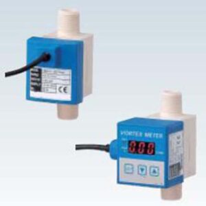
Biogas flowmeter Tap water flowmeter Electromagnetic flowmeter English vortex flowmeter Gas flowmeter
| Application | Flow Meter |
|---|---|
| Types of | Electronic |
| Installation method | Flange |
| Output method | digital, analog |
| Application | Factory |
Technical Specifications
| model | FMG-E | FMG-M | |
| All-in-one | Separate type | ||
| Dimensions (mm) | 15~2200 | ||
| App types | Chemical liquid, raw water, ordinary water, fire water Liquids with conductivity >20μS/cm |
||
| flow rate | 0.1~15.0 m/s | ||
| Conductivity | Greater than 20μS/cm | ||
| precision | ± 0.5% of reading | ||
| Repeatability | ± 0.25% of reading | ||
| Material of electrode and ground electrode | Molybdenum-containing stainless steel, Hastelloy B, Hastelloy C, titanium, tantalum, platinum-iridium alloy | ||
| Body material | carbon steel | ||
| Ground Ring Material | Stainless steel 1Cr18Ni9Ti | ||
| Protection ring material | DN15~DN600 | Stainless steel 1Cr18Ni9Ti | |
| DN700~DN2200 | carbon steel | ||
| With protective lining material Highest temperature resistance | Silicone Fluoroelastomer (FVMQ) | <70℃ | <180℃ |
| Polytetrafluoroethylene (PTFE) | <70℃ | <170℃ | |
| Tetrafluoroethylene (PFA) | <70℃ | <160℃ | |
| Polyvinyl Fluoride – Propylene (F46) | <70℃ | <160℃ | |
| Polychloroprene (CR) | <70℃ | <80℃ | |
| Polyurethane rubber (PU) | <70℃ | <80℃ | |
| Maximum withstand voltage | DN15~DN300 | 1.6Mpa | |
| DN350~DN500 | 1.0Mpa | ||
| DN600~DN2200 | 0.6Mpa | ||
| display panel | 3-column backlit OLED display | ||
| Protection level | IP68 measuring tube material and IP65 display panel | ||
| output signal | 4~20 mA or 0~10mA or pulse output | ||
| communication signal | RS485 (optional), WiFi+AIoT (optional) | ||
| Cloud APP (optional) | AIoT module with cloud APP | ||
| power supply | AC 85~265V 45~63Hz or DC 11~40V or 3.3V battery version | ||
| Consume power | <15W | ||
Flow range
| DN | Maximum withstand voltage | Flange size (mm) | weight | Flow range (m3/h) | |||||
| (mm) | (Mpa) | L(PTFE) | L(Rubber/PFA/F46) | D | d1 | n*d0 | (kg) | Qmin(0.5m/s) | Qmax(15m/s) |
| 10 | 1.6 | 193 | / | 90 | 60 | 4*14 | 8.0 | 0.14 | 4.24 |
| 15 | 95 | 65 | 8.5 | 0.32 | 9.54 | ||||
| 20 | 105 | 75 | 9.5 | 0.57 | 16.96 | ||||
| 25 | 115 | 85 | 10 | 0.88 | 26.51 | ||||
| 32 | 135 | 100 | 4*18 | 11.5 | 1.45 | 43.43 | |||
| 40 | 200 | 145 | 110 | 12 | 2.26 | 67.86 | |||
| 50 | 160 | 125 | 14 | 3.53 | 106.03 | ||||
| 65 | 243 | 125 | 180 | 145 | 16 | 5.97 | 179.19 | ||
| 80 | 244 | 195 | 160 | 8*18 | 18 | 9.05 | 271.43 | ||
| 100 | 215 | 180 | 20 | 14.14 | 424.12 | ||||
| 125 | 245 | 210 | 24 | 22.09 | 662.68 | ||||
| 150 | 290 | 300 | 280 | 240 | 8*23 | 29 | 31.09 | 954.26 | |
| 200 | 341 | 350 | 335 | 295 | 12*23 | 37 | 56.55 | 1696.46 | |
| 250 | 441 | 450 | 405 | 355 | 12*26 | 52 | 88.36 | 2650.72 | |
| 300 | 490 | 500 | 460 | 400 | 72 | 127.23 | 3817.04 | ||
| 350 | 1.0 | 500 | 460 | 16*23 | 83 | 173.18 | 5195.41 | ||
| 400 | 565 | 515 | 16*26 | 100 | 226.19 | 6785.84 | |||
| 450 | 540 | 550 | 615 | 565 | 20*26 | 115 | 286.28 | 8588.33 | |
| 500 | 540 | 670 | 620 | 135 | 353.43 | 10602.88 | |||
| 600 | 0.6 | 590 | 600 | 755 | 705 | 20*25 | 165 | 508.94 | 15268.14 |
| 700 | 690 | 700 | 860 | 810 | 24*25 | 440 | 692.72 | 20781.64 | |
| 800 | 790 | 800 | 975 | 920 | 24*30 | 550 | 904.78 | 27143.36 | |
| 900 | 890 | 900 | 1075 | 1020 | 660 | 1145.11 | 34353.32 | ||
| 1000 | 990 | 1000 | 1175 | 1120 | 28*30 | 815 | 1413.72 | 42411.50 | |
| 1200 | 1190 | 1200 | 1400 | 1340 | 32*34 | 880 | 2035.75 | 61072.56 | |
| 1400 | 1390 | 1400 | 1620 | 1560 | 36*34 | 1240 | 2770.88 | 83126.54 | |
| 1600 | 1590 | 1600 | 1820 | 1760 | 40*34 | 1560 | 3617.11 | 108573.44 | |
| 1800 | 1790 | 1800 | 2046 | 1970 | 44*41 | 2090 | 4580.44 | 137413.26 | |
| 2000 | 1990 | 2000 | 2265 | 2180 | 48*48 | 2815 | 5654.87 | 169646.00 | |
| 2200 | 2190 | 2200 | 2475 | 2390 | 52*48 | 3215 | 6842.39 | 205217.66 | |
Size Chart

| DN | Maximum withstand voltage | Flange size (mm) | weight | Flow range (m3/h) | |||||
| (mm) | (Mpa) | L(PTFE) | L(Rubber/PFA/F46) | D | d1 | n*d0 | (kg) | Qmin(0.5m/s) | Qmax(15m/s) |
| 10 | 1.6 | 193 | / | 90 | 60 | 4*14 | 8.0 | 0.14 | 4.24 |
| 15 | 95 | 65 | 8.5 | 0.32 | 9.54 | ||||
| 20 | 105 | 75 | 9.5 | 0.57 | 16.96 | ||||
| 25 | 115 | 85 | 10 | 0.88 | 26.51 | ||||
| 32 | 135 | 100 | 4*18 | 11.5 | 1.45 | 43.43 | |||
| 40 | 200 | 145 | 110 | 12 | 2.26 | 67.86 | |||
| 50 | 160 | 125 | 14 | 3.53 | 106.03 | ||||
| 65 | 243 | 125 | 180 | 145 | 16 | 5.97 | 179.19 | ||
| 80 | 244 | 195 | 160 | 8*18 | 18 | 9.05 | 271.43 | ||
| 100 | 215 | 180 | 20 | 14.14 | 424.12 | ||||
| 125 | 245 | 210 | 24 | 22.09 | 662.68 | ||||
| 150 | 290 | 300 | 280 | 240 | 8*23 | 29 | 31.09 | 954.26 | |
| 200 | 341 | 350 | 335 | 295 | 12*23 | 37 | 56.55 | 1696.46 | |
| 250 | 441 | 450 | 405 | 355 | 12*26 | 52 | 88.36 | 2650.72 | |
| 300 | 490 | 500 | 460 | 400 | 72 | 127.23 | 3817.04 | ||
| 350 | 1.0 | 500 | 460 | 16*23 | 83 | 173.18 | 5195.41 | ||
| 400 | 565 | 515 | 16*26 | 100 | 226.19 | 6785.84 | |||
| 450 | 540 | 550 | 615 | 565 | 20*26 | 115 | 286.28 | 8588.33 | |
| 500 | 540 | 670 | 620 | 135 | 353.43 | 10602.88 | |||
| 600 | 0.6 | 590 | 600 | 755 | 705 | 20*25 | 165 | 508.94 | 15268.14 |
| 700 | 690 | 700 | 860 | 810 | 24*25 | 440 | 692.72 | 20781.64 | |
| 800 | 790 | 800 | 975 | 920 | 24*30 | 550 | 904.78 | 27143.36 | |
| 900 | 890 | 900 | 1075 | 1020 | 660 | 1145.11 | 34353.32 | ||
| 1000 | 990 | 1000 | 1175 | 1120 | 28*30 | 815 | 1413.72 | 42411.50 | |
| 1200 | 1190 | 1200 | 1400 | 1340 | 32*34 | 880 | 2035.75 | 61072.56 | |
| 1400 | 1390 | 1400 | 1620 | 1560 | 36*34 | 1240 | 2770.88 | 83126.54 | |
| 1600 | 1590 | 1600 | 1820 | 1760 | 40*34 | 1560 | 3617.11 | 108573.44 | |
| 1800 | 1790 | 1800 | 2046 | 1970 | 44*41 | 2090 | 4580.44 | 137413.26 | |
| 2000 | 1990 | 2000 | 2265 | 2180 | 48*48 | 2815 | 5654.87 | 169646.00 | |
| 2200 | 2190 | 2200 | 2475 | 2390 | 52*48 | 3215 | 6842.39 | 205217.66 | |
Application field
1. Monitoring of public water resources
*Legacy pipeline installation solution:
A large number of cloth-made plug-in electromagnetic flowmeters solve the requirements of convenience and speed without cutting pipes
*Meter reading record solution:
The integrated installation reduces the problem of borrowing space for different units in the public sector
2. Raw water metering of water works
*Legacy pipeline installation solution:
A large number of cloth-made plug-in electromagnetic flowmeters solve the requirements of convenience and speed without cutting pipes
*Meter reading record solution:
The integrated installation reduces the problem of borrowing space for different units in the public sector
3. Sewage treatment and sewage measurement
Sewage Discharge Solutions:
There is no need to install a flange interface in the construction of the underground pipeline, just insert the opening
c Maintenance cleaning solutions:
Retractable and easily removable sensor head for cleaning
*Emissions metering solutions:
Air traffic control alarm to know the emission status at any time and the cumulative usage status through RS485 signal transmission
4. Filling water metering for printing, dyeing and finishing machine
*Chemical solution:
The acid and alkali resistant sensor head with protective lining is more suitable for use in the liquid pipeline.
*Equipment Solutions:
After installing the front and back ends of the equipment, clearly understand the energy consumption status of the equipment and effectively evaluate the energy status of the whole plant
5. Circulating water monitoring in steel, thermal power and petrochemical plants
*Not sure about water quality installation solutions:
A large number of single types of protective lining grades are used to solve the opaque fluid situation of pipelines in the plant area
*Recycled water solutions:
On-site direct meter reading of the loop recovery pipeline and central monitoring of the cumulative recovery rate
6. Building property chilled water metering
*Building energy saving solutions:
Fast and convenient control of air-conditioning water in and out to improve energy consumption design of old buildings
*Sub-lease solution:
After the distribution pipeline is installed, the user's usage status is known in detail, and the display is used to solve the user's billing doubts
Order model
| Ordering Information | ||||||||||||||||||
| FMG | coding | Model type | ||||||||||||||||
| E | Integrated type (standard type) | |||||||||||||||||
| M | Separate type | |||||||||||||||||
| coding | Motor type | |||||||||||||||||
| N | Standard | |||||||||||||||||
| S | scraper type | |||||||||||||||||
| R | Detachable scraper type | |||||||||||||||||
| G | With ground level | |||||||||||||||||
| coding | size | |||||||||||||||||
| XXXX | 15~3000mm(1/2"~120") | |||||||||||||||||
| coding | Connection method | |||||||||||||||||
| 0 | PN16(standard type) | |||||||||||||||||
| 1 | PN10 (applicable to >DN300) | |||||||||||||||||
| 2 | PN6 (applicable to >DN600) | |||||||||||||||||
| A | ANSI 300# (applicable to >DN300) | |||||||||||||||||
| B | ANSI 150# (applicable to >DN600) | |||||||||||||||||
| J | JIS20K (applicable to >DN300) | |||||||||||||||||
| K | JIS10K (applicable to >DN600) | |||||||||||||||||
| coding | Electrode material | |||||||||||||||||
| 0 | Molybdenum-containing stainless steel (standard type) | |||||||||||||||||
| 1 | Hastelloy B | |||||||||||||||||
| 2 | Hastelloy C | |||||||||||||||||
| 3 | Titanium (Ti) | |||||||||||||||||
| 4 | Tantalum (Ta) | |||||||||||||||||
| 5 | Platinum-iridium alloy (Pt) | |||||||||||||||||
| 6 | Stainless Steel Coated Tungsten Carbide | |||||||||||||||||
| coding | Protective lining material | |||||||||||||||||
| 0 | None (standard type) | |||||||||||||||||
| 1 | Polytetrafluoroethylene (PTFE) | |||||||||||||||||
| 2 | Tetrafluoroethylene (PFA) | |||||||||||||||||
| 3 | Polyethylene fluoride-propylene (F46) | |||||||||||||||||
| 4 | Polychloroprene (CR) | |||||||||||||||||
| 5 | Polyurethane rubber (PU) | |||||||||||||||||
| 6 | Silicone Fluoroelastomer (FVMQ) | |||||||||||||||||
| coding | Pressure resistance | |||||||||||||||||
| 0 | 1.6Mpa for DN15~DN300 (standard type) | |||||||||||||||||
| 1 | 1.0Mpa for DN350~DN500 | |||||||||||||||||
| 2 | 0.6Mpa for DN600~DN2200 | |||||||||||||||||
| coding | output signal | |||||||||||||||||
| A | 4~20 mA+pulse output+RS-485 MODBUS communication (standard type) | |||||||||||||||||
| H | WiFi+AIoT communication | |||||||||||||||||
| coding | Temperature resistant | |||||||||||||||||
| 0 | .~70 ℃ (standard type) | |||||||||||||||||
| 0 | .~100 ℃ (applicable to separated type with lining material) | |||||||||||||||||
| 0 | .~180 ℃ (applicable to separated type with lining material) | |||||||||||||||||
| coding | panel interface | |||||||||||||||||
| N | Chinese Traditional (Standard) | |||||||||||||||||
| I | English | |||||||||||||||||
| coding | connecting line | |||||||||||||||||
| N | Integrated type without cable (standard type) | |||||||||||||||||
| R | Separate type with 10m cable | |||||||||||||||||
| coding | Power Supply | |||||||||||||||||
| N | AC 85~265V 45~63Hz (standard type) | |||||||||||||||||
| R | DC 11~40V | |||||||||||||||||
| B | 3.3V battery model | |||||||||||||||||
| coding | label | |||||||||||||||||
| F | FGT® brand (standard type) | |||||||||||||||||
| N | Customized brand | |||||||||||||||||
| coding | Certification documents | |||||||||||||||||
| F | FGT® Certification | |||||||||||||||||
| I | ilac-MRA® Third Party Certification | |||||||||||||||||
| FMG | Complete order model | |||||||||||||||||
| *Note: The annual purchase order of the customized brand needs to be more than 100 sets | ||||||||||||||||||
meet design standards
meet design standards
meet design standards
- EX
- IP67
- CE
- IEC
- SGS
- ilac-MAR
- TAF
Support communication protocol
- NB-IOT
- MODBUS-RTU
- ZIGBEE

