FGT think your best choice in the future
System Integration Designers in FGT
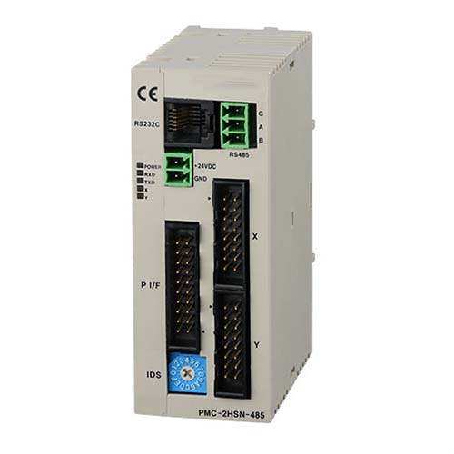
2-axis complementary/standard programmable motion controller Model PMC-2HSN/2HSP series | Autonics brand
Autonics Brand: PMC-2HSP/2HSN series programmable motion controllers have high-speed independent 2-axis stepper motor control. The PMC-2HSP model supports linear and arc complementary control. 17 control instructions (PMC-2HSN: 13 instructions) can carry out 200 steps of operation programming, and there are 4 operating modes. Multiple stepper motor control of up to 32 axes (16 units) can be achieved through RS485 communication
Autonics Brand: PMC-2HSP/2HSN series programmable motion controllers feature high-speed independent 2-axis stepper motor control with processing speeds up to 4 Mpps. The PMC-2HSP model supports linear and arc complementary control. 17 control instructions (PMC-2HSN: 13 instructions) can perform 200 steps of operation programming, and there are 4 operation modes (scan, continuous, index, program). Multiple stepper motor control of up to 32 axes (16 units) can be achieved through RS485 communication (Modbus RTU)
Autonics PMC-2HSN is a motion controller manufactured by Autonics. Here are some key features and information about Autonics PMC-2HSN:
Number of axes: 2 axes
Type: freestanding
Main features: S-shaped acceleration and deceleration
Input/output contacts: Parallel I/F: input 13, output 8
Please note that the Autonics PMC-2HSN is designed for independent 2-axis control of high operating speeds. If you need more specific details or have any other questions, please feel free to ask!
- High-speed independent 2-axis control with processing speeds up to 4 Mpps
- Supports linear and circular interpolation control (PMC-2HSP)
- 17 control commands and up to 200 steps of operation programming (PMC-2HSN series 13 commands, excluding linear and circular interpolation commands)
- Support multiple control interfaces (USB, RS232C, RS485, parallel I/O)
- Multiple control of up to 32 axes (16 units) using RS485 communication (Modbus RTU)
- 4 operating modes: Jog, Continuous, Index, Program
- Symmetrical/asymmetrical trapezoidal or S-shaped acceleration/deceleration control
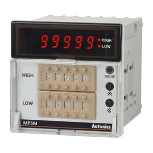
The principle of timer counter table | Our performance
Rotary encoderprinciple| Our performance
Principle of safety grating | Our performance
Stepper Motor &Drive principle | Our performance
stepper motor
In 1923, the British James (James Weir French) invented the three-phase variable reluctance type (Variable reluctance) stepping motor, referred to as "stepping motor". Stepper motor is a kind of pulse motor. After the DC power is processed by a digital IC, it becomes a pulse current to control the motor. Moreover, the motor rotates a circle and is divided into several equal parts (steps), which can make the control of the angle more precise.
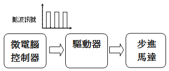
A stepping motor is a motor that advances step by step. It mainly includes a stator and a rotor with gear-like protrusions. The stator is wound with a (excitation) coil. By switching the current flow in the stator coil, a changing electromagnetic attraction is generated. At a certain angle Turn the rotor gradually. The control process of the stepper motor is shown in the figure below. The microcomputer controller generates the required pulse signal. When the signal is output from the microcomputer, the signal is amplified by the driver first, and the voltage signal controls the current on the stator coil, and then controls the motor operation. Angle. No feedback signal is used in the entire control process, which is called closed loop control, so no sensor is needed, which can reduce costs.
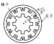
The stepping angle of the stepping motor, that is, the resolution of the stepping motor (the amount of rotation of one pulse), depends on the specifications of the stepping motor. For example, as shown in the figure below, the number of stators is 12, including A, B, C has 3 sets of coil windings, and the rotor has 8 salient poles.
Then the stepping angle of the stepping motor = 360° / (the number of coil groups × the number of rotor salient poles) = 15°. That is, each time a pulse signal is received, the stepper motor rotates 15°, and if 24 pulse signals are input, it can rotate once. Therefore, as long as the number of input pulses is controlled, the rotation angle of the motor can be determined.
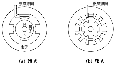
According to the structure, stepping motors can be divided into three types: permanent magnet PM type (permanent magnet type), variable reluctance VR type (variable reluctance type), and hybrid type. As shown in Figure (a) below, the rotor of PM type stepping motor is made of permanent magnets, and its characteristic is that when the stator coil is not energized (not excited), the rotor itself can still generate holding torque due to its magnetic properties. The stepping angle of PM type varies according to different rotor materials. For example, the stepping angle of AlNiCo-based magnet rotors is larger, which is 45° or 90°, while the stepping angle of ceramic-iron magnets can be multi-pole magnetized. Smaller, 7.5° and 15°; as shown in Figure (b), the rotor of the VR stepping motor is made of high magnetic permeability material, because the stator coil is used to generate attraction to make the rotor rotate, so when the coil is used The torque cannot be maintained when it is not energized. In addition, since the rotor can be designed to improve efficiency, the VR-type stepping motor can provide a large torque. It is usually used in machine tools that require large torque and precise positioning. The stepping angle of the motor is generally 15°; as for the compound stepping motor, many gear-shaped protruding electrodes are arranged on the periphery of the rotor, and permanent magnets are also installed in its axial direction, which can be regarded as a combination of PM type and VR type. , has the advantages of both PM type and VR type - high accuracy, high torque, but the step angle is small, generally between 1.8°~3.6°, most commonly used in OA equipment such as photocopiers, printers on a computer or photographic equipment.
Advantages of stepper motors:
(1) The system structure is simple, no position sensor is needed, so the cost is low
(2) The angle and speed are easy to control, and the speed is proportional to the input pulse frequency
(3) High repeatability and positioning accuracy, no angle accumulation error
(4) High holding torque when stationary
Disadvantages of stepper motors:
(1) In the event of stall or step loss, correction and compensation cannot be made immediately
(2) Vibration or resonance is easy to occur at a certain frequency
Stall means that when the rotation speed of the motor rotor cannot keep up with the stator excitation speed, the motor rotor stops rotating. The phenomenon of motor stall may occur in all kinds of motors. In general motor applications, when stall occurs, the coil is often burned. However, when a stepper motor stalls, it will only cause the motor to stand still. Although the coil is still being excited, But because it is a pulse signal, it will not burn the coil.
Loss of step is due to the fact that the output torque is inversely proportional to the rotational speed when the speed is increased instantaneously during the operation of the motor, so the torque drop cannot load the external load, resulting in a small slippage. Out-of-step situation occurs only with stepper motor, and out-of-step can be prevented by adjusting the acceleration control program of the motor.
The application of the motor will be quite wide, such as the positioning of the magnetic head in the hard disk drive and the floppy disk drive, and the paper transmission of the printer, fax machine, and photocopier. In these products, the motor will be the key component. In the future development, how to develop micro-precision motors that are thin, short and easy to dissipate heat will be an important issue.
Further reading:Improving production efficiency and reducing failure rates: Autonics Taiwan distributors help companies strengthen their competitiveness

