FGT think your best choice in the future
System Integration Designers in FGT
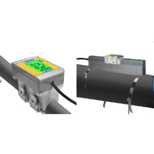
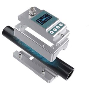
UFMC Type: Pinch Tube Ultrasonic Flow Meter | Discontinued
UFMC Type: Pinch Ultrasonic Flowmeter|Application: Pure water cleaning wet process PCB board|RO pure water treatment equipment|Tap water pipeline flow transparent design|non-contact pipeline design|organic solvent pipeline installation|wisdom Building energy-saving water equipment installation|Swimming pool treatment equipment
- Applicable pipe diameter: Φ20(DN15), Φ25(DN20), Φ32(DN25), Φ40(DN32), Φ50(DN40), Φ63(DN50)
- Description
- Additional information
- Technical Specifications
- Application field
- Flow range
- Order model
- Special needs
- Inquire now
UFMC Type: Pinch Tube Ultrasonic Flow Meter | Discontinued
- Flow range: 0.1~±6m/s
- Accuracy: ±1.5%FS
- Repeatability: 0.3%
- Applicable pipe diameter: DN15~DN300
- Detection fluid: water
- Applicable piping material: UPVC/carbon steel/stainless steel
- Protection class: IP67
Pinch Tube Ultrasonic Flow Meter
Jump to navigationJump to search
Pinch Tube Ultrasonic Flow Meteris a flow meter that measures the velocity of a fluid ultrasonically to calculate volume flow. Using an ultrasonic transducer, the flowmeter can measure the average velocity along the ultrasonic launch path by averaging the difference in travel time or by measuring the frequency shift between the ultrasonic pulses propagating into and opposite the direction of flow from the Doppler effect. Ultrasonic flow meters are affected by the acoustic properties of the fluid and may be affected by temperature, density, viscosity, and suspended particulate matter, depending on the exact flow meter. Their purchase price varies widely, but since, unlike mechanical flow meters, they use no moving parts, they are generally inexpensive to use and maintain.
Detection type
There are three different types ofUltrasonic flowmeter. Transmission (or time-of-flight) flow meters can be divided into in-line (intrusive, wet) flow meters and pinch-pipe (non-intrusive) flow meters. Ultrasonic flowmeters that use Doppler shift are called reflection flowmeters or Doppler flowmeters. The third type is the open channel flowmeter.[1]
principle
Time-shift detection method flowmeter
Ultrasonic flowmeterThe difference between the travel times of the ultrasonic pulses propagating in the opposite direction to the flow direction is measured. This time difference is a measure of the average velocity of the fluid along the path of the ultrasound beam. By using the sum of absolute transit times, the average fluid velocity and sound velocity can be calculated. Using these two transit times, the distance between the receiving and transmitting transducers and the angle of inclination, if we assume that the sound must oppose the flow as it rises and the flow as it descends, we can by definition write the following etc. speed
and
By adding and subtracting the above equations, we get
and
where is the average velocity of the fluid along the sound path and is the speed of sound.
Doppler frequency movement detection method flowmeter
Another method of ultrasonic flow measurement is to use the Doppler shift, which is caused by the reflection of the ultrasonic beam from ultrasonically reflective materials (such as solid particles or entrained air bubbles in the flowing fluid) or the fluid itself. caused by turbulence. Liquid is clean.
Doppler ultrasonic flowmeter is used for mud, liquid with bubbles, gas with sound reflecting particles.
This type of ultrasonic flowmeter can also be used to measure blood flow rate by passing an ultrasonic beam through tissue, reflecting it off a reflector, reversing the direction of the beam and repeating the measurement to determine the rate of blood flow. amount can be estimated. The frequency of the transmitted beam is affected by the movement of blood in the blood vessel, and by comparing the frequencies of the upstream and downstream beams, blood flow through the blood vessel can be measured. The difference between the two frequencies is a measure of the true volumetric flow. Wide beam sensors can also be used to measure flow regardless of the cross-sectional area of the vessel.
Open Channel Flow Meter
In this case, the ultrasonic element is actually measuring the height of the water in the open channel. Depending on the geometry of the channel, the flow can be determined from the height. Ultrasonic sensors usually also have temperature sensors, because the speed of sound in air is affected by temperature.
Pinch Tube Ultrasonic Flow MeterApplication Notes for
used fortransit timeclamp typeUltrasonic flowmeter
Make sure the fluid conducts the ultrasonic waves adequately, as the flow meter will not be able to measure when the ultrasonic waves cannot penetrate the flow between the transducers. Likewise, ultrasonic waves must be able to penetrate the fluid for the Doppler flowmeter to function accurately. When the fluid is relatively opaque and impermeable to the fluid, Doppler flowmeters tend to measure fluid velocity at or near the pipe wall, which can cause significant measurement errors and/or cause flowmeter failure.
used forDoppler Clamp Type Ultrasonic Flowmeter
Make sure the fluid reflects the ultrasonic waves sufficiently, as the flowmeter will not operate without a reflected ultrasonic signal. Depending on the design, reflections may occur due to small air bubbles in the airflow or vortices in the airflow. These reflection sources are difficult to generate in practice if they do not already exist in a flowing stream. Fortunately, some combination of air bubbles and/or eddies is present in most applications.
The velocity of the solid particles in the slurry may differ from the velocity of its liquid carrier. Use ultrasonic technology with caution when solid particles may become concentrated in a portion of the flowing stream (for example, in a horizontal pipe flowing at relatively low velocities). Be careful when using a Doppler ultrasonic flowmeter in slurry applications, as solid particles can produce a strong signal, which can cause the Doppler flowmeter to measure the velocity of the solid rather than the liquid.
Avoid liquids that wet the transducer or do not wet the wall in front of the transducer, as the flow meter will not be able to measure when ultrasonic waves cannot enter the flow. Make sure to maintain a reliable clamp-on transducer connection on the pipe wall, as the flow meter will not be able to measure when the ultrasonic waves cannot reach the fluid.
Make sure you understand the process and use these flow meters correctly. For example, a periodic cleaning process upstream may cause the flowmeter to stop working because the dust may not allow the ultrasonic energy to pass through the fluid. Also, if dirt covers the wetted transducer, the flowmeter may not operate until it is cleaned.
how to usePinch Tube Ultrasonic Flow Meter
Pinch Tube Ultrasonic Flow MeterCommonly used to measure the velocity of liquids that allow ultrasonic waves to pass through, such as water, molten sulfur, cryogenic liquids, and chemicals. The transit time design can also be used to measure gas and steam flow. Be careful as fluids that do not transmit ultrasonic energy, such as many types of slurries, limit the penetration of ultrasonic waves into the fluid. In a Doppler ultrasonic flowmeter, the opaque fluid restricts the penetration of ultrasonic waves near the pipe wall, which reduces accuracy and/or renders the flowmeter unmeasurable. Time-of-flight ultrasonic flow meters may not work when the opaque liquid attenuates the ultrasonic waves to such an extent that the ultrasonic waves cannot reach the receiver.
Typical application industries
By industry, they are oil and gas, water and wastewater, power, chemicals, food and beverages, pharmaceuticals, metals and mining, and pulp and paper.
| Application | Flow Meter |
|---|---|
| Types of | Electronic |
| Installation method | Clamp on |
| Output method | digital, analog |
Technical Specifications
| model | UFMC | UFMV |
| Flow range (m/s) | 0~6 | 0~6 |
| precision | ±1.5 % FS | |
| Repeatability | ±0.3 % FS | |
| Measuring medium | water | |
| operating temperature | -10℃~+50℃ | |
| Take over size | DN15~DN50 | DN65-DN300 |
| Take over material | UPVC/carbon steel/stainless steel | |
| Installation method | Buckle type | rail type |
| Flow signal output | 4~20mA or RS485 or Wireless(Zigbee 2.4G) | |
| Supply voltage | DC24V/1A | |
Application field
Pinch Tube Ultrasonic Flow MeterApplication Notes for
used fortransit timeclamp typeUltrasonic flowmeter
Make sure the fluid conducts the ultrasonic waves adequately, as the flow meter will not be able to measure when the ultrasonic waves cannot penetrate the flow between the transducers. Likewise, ultrasonic waves must be able to penetrate the fluid for the Doppler flowmeter to function accurately. When the fluid is relatively opaque and impermeable to the fluid, Doppler flowmeters tend to measure fluid velocity at or near the pipe wall, which can cause significant measurement errors and/or cause flowmeter failure.
used forDoppler Clamp Type Ultrasonic Flowmeter
Make sure the fluid reflects the ultrasonic waves sufficiently, as the flowmeter will not operate without a reflected ultrasonic signal. Depending on the design, reflections may occur due to small air bubbles in the airflow or vortices in the airflow. These reflection sources are difficult to generate in practice if they do not already exist in a flowing stream. Fortunately, some combination of air bubbles and/or eddies is present in most applications.
The velocity of the solid particles in the slurry may differ from the velocity of its liquid carrier. Use ultrasonic technology with caution when solid particles may become concentrated in a portion of the flowing stream (for example, in a horizontal pipe flowing at relatively low velocities). Be careful when using a Doppler ultrasonic flowmeter in slurry applications, as solid particles can produce a strong signal, which can cause the Doppler flowmeter to measure the velocity of the solid rather than the liquid.
Avoid liquids that wet the transducer or do not wet the wall in front of the transducer, as the flow meter will not be able to measure when ultrasonic waves cannot enter the flow. Make sure to maintain a reliable clamp-on transducer connection on the pipe wall, as the flow meter will not be able to measure when the ultrasonic waves cannot reach the fluid.
Make sure you understand the process and use these flow meters correctly. For example, a periodic cleaning process upstream may cause the flowmeter to stop working because the dust may not allow the ultrasonic energy to pass through the fluid. Also, if dirt covers the wetted transducer, the flowmeter may not operate until it is cleaned.
how to usePinch Tube Ultrasonic Flow Meter
Pinch Tube Ultrasonic Flow MeterCommonly used to measure the velocity of liquids that allow ultrasonic waves to pass through, such as water, molten sulfur, cryogenic liquids, and chemicals. The transit time design can also be used to measure gas and steam flow. Be careful as fluids that do not transmit ultrasonic energy, such as many types of slurries, limit the penetration of ultrasonic waves into the fluid. In a Doppler ultrasonic flowmeter, the opaque fluid restricts the penetration of ultrasonic waves near the pipe wall, which reduces accuracy and/or renders the flowmeter unmeasurable. Time-of-flight ultrasonic flow meters may not work when the opaque liquid attenuates the ultrasonic waves to such an extent that the ultrasonic waves cannot reach the receiver.
Typical application industries
By industry, they are oil and gas, water and wastewater, power, chemicals, food and beverages, pharmaceuticals, metals and mining, and pulp and paper.
Flow range
| model | UFMC | UFMV |
| Flow range (m/s) | 0~6 | 0~6 |
| precision | ±1.5 % FS | |
| Repeatability | ±0.3 % FS | |
| Measuring medium | water | |
| operating temperature | -10℃~+50℃ | |
| Take over size | DN15~DN50 | DN65-DN300 |
| Take over material | UPVC/carbon steel/stainless steel | |
| Installation method | Buckle type | rail type |
| Flow signal output | 4~20mA or RS485 or Wireless(Zigbee 2.4G) | |
| Supply voltage | DC24V/1A | |
Order model
| Ordering Information | |||||||
| UFM | coding | type of installation | |||||
|
|
C | Buckle type (for DN15~DN65 use) | |||||
| V | V-rail type (for DN65~DN300) | ||||||
|
|
coding | output signal type | |||||
| 1 | 4~20mA (standard type) | ||||||
| 2 | RS485 | ||||||
|
Wireless (Zigbee 2.4G) | ||||||
| coding | Nozzle size type | ||||||
| 0 | DN15 (for buckle test use) | ||||||
| 1 | DN20 (for buckle test use) | ||||||
| 2 | DN25 (for buckle test use) | ||||||
| 3 | DN32 (for buckle test type) | ||||||
| 4 | DN40 (for buckle test use) | ||||||
| 5 | DN50V (for button test type) | ||||||
| 6 | DN65V (for V-rail type use) | ||||||
| 7 | DN80 (for V-rail type use) | ||||||
| 8 | DN100 (for V-rail type use) | ||||||
| 9 | DN150 (for V-rail type use) | ||||||
| 10 | DN200 (for V-rail type use) | ||||||
| 11 | DN250 (for V-rail type use) | ||||||
| 12 | DN300 (for V-rail type use) | ||||||
|
|
coding | Brand type | |||||
| F | FGT Logo (standard type) | ||||||
|
Customized brand | ||||||
| UFM | Complete order model | ||||||
| *Note: All models use supply voltage (+24Vdc/1A) | |||||||
| *Note: The number of orders placed with a customized label must reach 100 sets for more than one year | |||||||

