FGT think your best choice in the future
System Integration Designers in FGT
- 常用參數可自由排列到常用位置
- T/C,RTD.線性輸入可選
- 自動/手動控制模式可選
- 雙工輸出模式(加熱/冷卻)通過2個控製過程
- 警報 最多 3 個警報設置
- CT加熱器斷線報警
- 可編程模式多達 8 個斜坡/保溫段
- 可在 90V AC 至 260V AC、50/60Hz 的任何線路電壓下運行
- 可選 RS232 和 RS485 通訊接口 Modbus RTU 可用
- 開環電機閥控制
- 遠程設定點
- 軟啟動 重傳輸出
| 應用 | 溫度 |
|---|---|
| 類型 | 電子式 |
| 安裝方式 | 盤面 |
| 輸出方式 | 數位, 開關, 類比 |
Technical Specifications
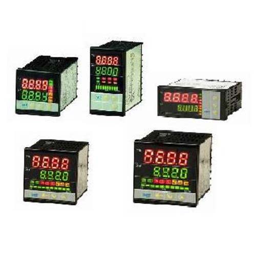
| Model | TPC484 | TPC489 | TPC964 | TPC727 | TPC969 | |
| Dimension(WxD) | 48x48mm | 48x96mm | 96x48mm | 72x72mm | 96x96mm | |
| Input Type | Termocouple | K,J,R,S,B,E,N,T,W3,W5,PL-II(Input impedance:Approx.1MΩ | ||||
| RTD | PT-100(DIN),JPT-100(JIS) | |||||
| Linear Analog | 0~10mV,0~20mV,0~50mV,4~20mA,0~10V…Please refer to Input Type List. | |||||
| Controlling Output | Relay | A Contact 5A/250V | A,B contact 8A/250V | |||
| Logic Voltage | PWM Pulse voltage(to drive SSR):On=24V;Off=0V(20mA Max.) | |||||
| Linear Analog | Currect:0~20mA,4~20mA(Inputimedance:600Ω Max.) Voltage:0~5V,1~5V,0~10V,2~10V(Inputimpedance:1KΩ Min.)Resolution:Approx.1,000 scales | |||||
| Controlling Method | Controlling selection of ON/OFF,P,PI,PD,PID | |||||
| Accuracy | 0.2%FS±1DIG(except thermocouple type B&S) | |||||
| Alarm Output | Relay Contact 8A,250VAC | |||||
| Data Backup Memory | EEPROM,10Years | |||||
| Storage/Operating Environment | 0~65℃/0~50℃,20~90%RH | |||||
| Digi Height(mm) | PV(Red) | 8 | 8 | 13 | 14 | 14 |
| SV(Green) | 8 | 8 | 10 | 10 | 10 | |
| Power Consumption(Approx.) | 4VA | 4VA | 4VA | 5VA | 5VA | |
| Power Supply | AC 90~240V(60/50Hz),DC24V(optional) | |||||
| Net Weight(Approx.) | 130g | 200g | 200g | 200g | 280g | |
Application
What is PID Controller
A proportional–integral–derivative controller (PID controller. or three-term controller) is a control loop mechanism employing feedback that is widely used in industrial control systems and a variety of other applications requiring continuously modulated control. A PID controller continuously calculates an error value as the difference between a desired setpoint (SP) and a measured process variable (PV) and applies a correction based on proportional, integral, and derivative terms (denoted P, I, and D respectively), hence the name.
In practical terms it automatically applies accurate and responsive correction to a control function. An everyday example is the cruise control on a car, where ascending a hill would lower speed if only constant engine power were applied. The controller’s PID algorithm restores the measured speed to the desired speed with minimal delay and overshoot by increasing the power output of the engine.
The first theoretical analysis and practical application was in the field of automatic steering systems for ships, developed from the early 1920s onwards. It was then used for automatic process control in the manufacturing industry, where it was widely implemented in pneumatic, and then electronic, controllers. Today the PID concept is used universally in applications requiring accurate and optimised automatic control.
PID controller application
In theory, a controller can be used to control any process which has a measurable output (PV), a known ideal value for that output (SP) and an input to the process (MV) that will affect the relevant PV. Controllers are used in industry to regulate temperature, pressure, force, feed rate,[15]flow rate, chemical composition (component concentrations), weight, position, speed, and practically every other variable for which a measurement exists.
1.Environmental control
2.Smart Manufacturing Automation
Size Rang
| Model | TPC484 | TPC489 | TPC964 | TPC727 | TPC969 | |
| Dimension(WxD) | 48x48mm | 48x96mm | 96x48mm | 72x72mm | 96x96mm | |
| Input Type | Termocouple | K,J,R,S,B,E,N,T,W3,W5,PL-II(Input impedance:Approx.1MΩ | ||||
| RTD | PT-100(DIN),JPT-100(JIS) | |||||
| Linear Analog | 0~10mV,0~20mV,0~50mV,4~20mA,0~10V…Please refer to Input Type List. | |||||
| Controlling Output | Relay | A Contact 5A/250V | A,B contact 8A/250V | |||
| Logic Voltage | PWM Pulse voltage(to drive SSR):On=24V;Off=0V(20mA Max.) | |||||
| Linear Analog | Currect:0~20mA,4~20mA(Inputimedance:600Ω Max.) Voltage:0~5V,1~5V,0~10V,2~10V(Inputimpedance:1KΩ Min.)Resolution:Approx.1,000 scales | |||||
| Controlling Method | Controlling selection of ON/OFF,P,PI,PD,PID | |||||
| Accuracy | 0.2%FS±1DIG(except thermocouple type B&S) | |||||
| Alarm Output | Relay Contact 8A,250VAC | |||||
| Data Backup Memory | EEPROM,10Years | |||||
| Storage/Operating Environment | 0~65℃/0~50℃,20~90%RH | |||||
| Digi Height(mm) | PV(Red) | 8 | 8 | 13 | 14 | 14 |
| SV(Green) | 8 | 8 | 10 | 10 | 10 | |
| Power Consumption(Approx.) | 4VA | 4VA | 4VA | 5VA | 5VA | |
| Power Supply | AC 90~240V(60/50Hz),DC24V(optional) | |||||
| Net Weight(Approx.) | 130g | 200g | 200g | 200g | 280g | |
Order Information
| Order Information | ||||||||||||||
| TPC | Code | Dimension Size Type | ||||||||||||
|
|
484 | 48x48mm | ||||||||||||
| 489 | 48x96mm | |||||||||||||
| 964 | 96x48mm | |||||||||||||
| 727 | 72x72mm | |||||||||||||
| 969 | 96x96mm | |||||||||||||
|
|
Code | Input Type | ||||||||||||
| 0 | Thermocouple(Standard Type) | |||||||||||||
| 1 | RTD | |||||||||||||
| 2 | 4~20mA | |||||||||||||
| 3 | 0~5Vdc | |||||||||||||
| 4 | 1~5V | |||||||||||||
| 5 | 0~10V | |||||||||||||
|
2~10V | |||||||||||||
| Code | Output#1 Type | |||||||||||||
| 0 | Null | |||||||||||||
| 1 | Relay(Standard Type) | |||||||||||||
| 2 | Logic Voltage(SSR Control) | |||||||||||||
| 3 | 4~20mA | |||||||||||||
| 4 | 0~5V | |||||||||||||
| 5 | 1~5V | |||||||||||||
| 6 | 0~10V | |||||||||||||
| 7 | 2~10V | |||||||||||||
| 8 | 3-line proportional motor controlling | |||||||||||||
|
|
Code | Output#2 Type | ||||||||||||
| 0 | Null(Standard Type) | |||||||||||||
| 1 | Relay | |||||||||||||
| 2 | Logic Voltage(SSR control) | |||||||||||||
| 3 | 4~20mA | |||||||||||||
| 4 | 0~5V | |||||||||||||
| 5 | 1~5V | |||||||||||||
| 6 | 0~10V | |||||||||||||
| 7 | 2~10V | |||||||||||||
|
|
Code | Alarm Type | ||||||||||||
| 0 | Null(Standard Type) | |||||||||||||
| 1 | 1 Set | |||||||||||||
| 2 | 2 Sets | |||||||||||||
| 3 | 3 Sets | |||||||||||||
| A | HBA(50A)*1 | |||||||||||||
| B | HBA+AL2 | |||||||||||||
| C | HBA+AL2,3 | |||||||||||||
| D | HBA(100A) | |||||||||||||
| E | HBA+AL2 | |||||||||||||
| F | HBA+AL2,3 | |||||||||||||
|
|
Code | Transmitting Output Type | ||||||||||||
| 0 | Null(Standard Type) | |||||||||||||
| 3 | 4~20mA | |||||||||||||
| 4 | 0~5V | |||||||||||||
| 5 | 1~5V | |||||||||||||
| 6 | 0~10V | |||||||||||||
| 7 | 2~10V | |||||||||||||
|
|
Code | Remove SV Type | ||||||||||||
| 0 | Null(Standard Type) | |||||||||||||
| 3 | 4~20mA | |||||||||||||
| 4 | 0~5V | |||||||||||||
| 5 | 1~5V | |||||||||||||
| 6 | 0~10V | |||||||||||||
| 7 | 2~10V | |||||||||||||
|
|
Code | Communication Type | ||||||||||||
| 0 | Null(Standard Type) | |||||||||||||
| 1 | RS232 | |||||||||||||
| 2 | RS485 | |||||||||||||
|
|
Code | Water Proof Type | ||||||||||||
| N | No Blank(Standard Type) | |||||||||||||
| P | Yes | |||||||||||||
|
|
Code | Power Supply Type | ||||||||||||
| A | AC 90~240V(Standard Type) | |||||||||||||
| D | DC/AC 24~40V | |||||||||||||
|
|
Code | Logo | ||||||||||||
| F | FGT Logo(Standard Type) | |||||||||||||
| C | Customer Logo | |||||||||||||
|
|
||||||||||||||
| TPC | Complete Ordering Code | |||||||||||||
| *Note:If HBA function is available,AL1 function will be disabled.Select suitable amperage(50 or 100A) according to the load currect magnitude. | ||||||||||||||
| *Note:HBA and RSV cannot be allocated together. | ||||||||||||||
| *Note:Using customer Logo launch to more than 100 united for one year | ||||||||||||||

